Introduce ..
This is an advanced feature that allows users to interfere into the output controller by pin mapping on ESP32 to ESPrtk ..
In this way, the selection and placement of the output pins on ESP32 will not depend on the default configuration, making it easier for users to redesign their own ESPrtk PCB board.
This is a system configure and it is hidden when accessed in the Web Configure.
To be able to access this page, after the login Profile, type http://192.168.4.1/system to enter System page.
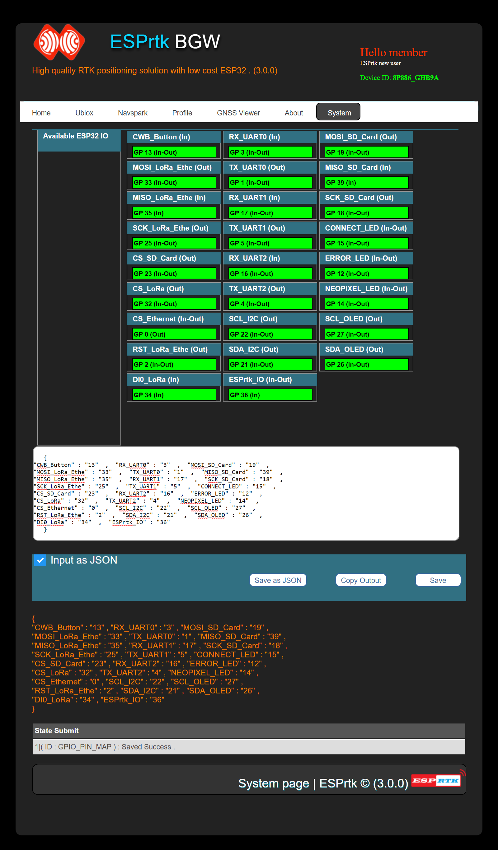
This page showing with a black background interface , users can drag and drop ESP32 pins into the frame corresponding to ESPrtk. Click “Save” button to save the configuration.
Or user can enter the JSON string into the text field and click “Save as JSON” to save the configuration.
After that, ESPrtk will check the logic, if there is no error, it will print “Config GPIO save success” in the Submit status box.
At the same time, it export a JSON string, clicks “Copy output” to save it in Clipboard as text and paste it anywhere.
Configure data will store in FLash in ESP32 .
Video
Default config from ESPrtk Factory (JSON):
This is the default configuration on ESPrtk, you may need it to restore to the default configuration state, just Copy it, paste it into the JSON box and click “Save as JSON”.
(Copy all text in box)
The above configuration will correspond to the diagram below:

Please read ESPrtk datasheet for detail information about pinout on ESPrtk.
Application .
Besides helping make PCB design more flexible, this feature allows ESPrtk to be compatible on all hardware boards with different pinout designs.
For example #1: WEMOS / Lolin ESP32 OLED board.
This module is integrated OLED LCD on GPIO5 (SDA_2) and GPIO4 (SCL_2) on board ( ESPrtk also supports OLED display ).
However, by default pin GPIO5 and GPIO4 on ESP32 are TX_UART1 and TX_UART2 of ESPrtk (see default JSON above) so we will swap the configuration on 6 pin, specifically:
- SCL_OLED : from 27 to 4
- SDA_OLED : from 26 to 5
- TX_UART2 : from 4 to 25
- TX_UART1 : from 5 to 26
- RX_UART1 : from 17 to 36
- RX_UART3 : from 36 to 17
And other pins remain the same as default.
The JSON code should be :
(copy all text in box)
The above configuration will correspond to the board below:

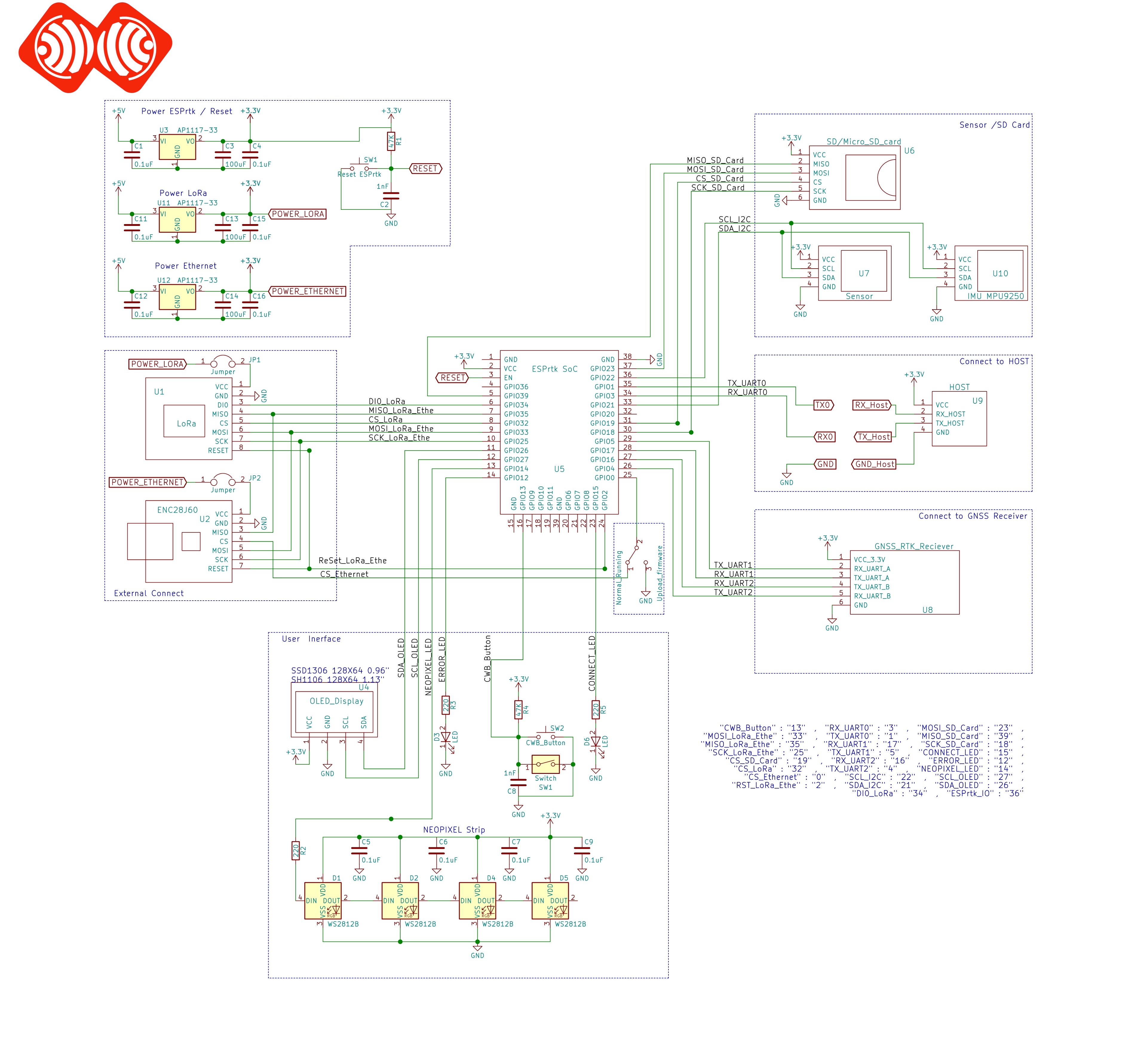
Connect with some componant as ESPrtk standard :

Then , you can connect it to the GNSS RTK modules here:
Connect ESPrtk with RTK Receiver and some other modules.
Note : this board only has 23 GPio Pin , so we cannot add SPI and I2C pin on it , that mean Ethernet and SD Card cannot use on this board !
Attention :
The ESP32-PICO chip is currently not supported on version 3.9.x.
You should use the chip ESP32-D0W0.
Support for TTGO boards with CHIP PICO is currently only available on version 3.2.5.
For example #2: LILYGO® TTGO LoRa32 V2.1 ESP32 433 MHz / 868 MHz / 915 MHz OLED 0.96 Inch SD Card Bluetooth WIFI Mô-đun SMA IP5306 + Custom Pinmap.

Attention :
The ESP32-PICO chip is currently not supported on version 3.9.x.
You should use the chip ESP32-D0W0.
Support for TTGO boards with CHIP PICO is currently only available on version 3.2.5.
The JSON code should be :
(copy all text in box)
Attention :
The ESP32-PICO chip is currently not supported on version 3.9.x.
You should use the chip ESP32-D0W0.
Support for TTGO boards with CHIP PICO is currently only available on version 3.2.5.
The above configuration will correspond to the board below:


Then , you can connect it to the GNSS RTK modules here:
Connect ESPrtk with RTK Receiver and some other modules.
- Make sure you changed Type CHIP ESP32 PICO before using. Go to http://192.168.4.1/system. , Then choose type CHIP ESP32 is ESP32 PICO D4 -> Press Save.
- We cannot using CONNECT_LED and NEOPIXEL_LED on this board !
- An additional piece of aluminum heatsink should be placed on CHIP ESP32 PICO to avoid temperature issues.
- Most GPIO pins (5/18/19/23/26/27) for SPI-LoRa are not connect to external output pins , if you plan to test Ethernet on this board, you need to connect the SPI-Ethernet interface directly with the pins on the LoRa module.
- The CWB Button now change from GPIO13 to GPIO36.
- You should also know: On this board, 2 pins GPIO04 / GPIO12 (for TX_UART1 / 2) are also connected to 2 Data2 / Data3 pins of the SD card slot. In fact, ESPrtk never uses these two Data2 / Data3 pins of a memory card.
Exceptions .
ESPrtk supports changing all output pins. However, not all configurations are accepted.
-Some GPio pins of ESP32 cannot be used for ESPrtk if it does not fully support. See table below
| GPio (ESP32) | …map to ESPrtk ( Input ) | .. map to ESPrtk ( Output ) |
| Input-Output | Yes | Yes |
| Input Only | Yes | No |
| Output Only | No | Yes |
Sometime the configuration is successfully saved (passes the Logic test) but ESPrtk will fail or not work properly, this depends on how the user configures and how ESP32 work with that configuration.
So users need to know the limitations of output pin on ESP32. Below is a brief summary ( see detail tutorial here https://randomnerdtutorials.com/esp32-pinout-reference-gpios/ )
| GPIO (ESP32) | Input | Output | Notes |
| 0 | pulled up | OK | outputs PWM signal at boot |
| 1 | TX pin | OK | debug output at boot |
| 2 | OK | OK | connected to on-board LED |
| 3 | OK | RX pin | HIGH at boot |
| 4 | OK | OK | |
| 5 | OK | OK | outputs PWM signal at boot |
| 6 | x | x | connected to the integrated SPI flash |
| 7 | x | x | connected to the integrated SPI flash |
| 8 | x | x | connected to the integrated SPI flash |
| 9 | x | x | connected to the integrated SPI flash |
| 10 | x | x | connected to the integrated SPI flash |
| 11 | x | x | connected to the integrated SPI flash |
| 12 | OK | OK | boot fail if pulled high |
| 13 | OK | OK | |
| 14 | OK | OK | outputs PWM signal at boot |
| 15 | OK | OK | outputs PWM signal at boot |
| 16 | OK | OK | |
| 17 | OK | OK | |
| 18 | OK | OK | |
| 19 | OK | OK | |
| 21 | OK | OK | |
| 22 | OK | OK | |
| 23 | OK | OK | |
| 25 | OK | OK | |
| 26 | OK | OK | |
| 27 | OK | OK | |
| 32 | OK | OK | |
| 33 | OK | OK | |
| 34 | OK | input only | |
| 35 | OK | input only | |
| 36 | OK | input only | |
| 39 | OK | input only |
Continue reading for a more detail and in-depth analysis of the ESP32 GPIOs and its functions.
Input only pins
GPIOs 34 to 39 are GPIs – input only pins. These pins don’t have internal pull-ups or pull-down resistors. They can’t be used as outputs, so use these pins only as inputs:
- GPIO 34
- GPIO 35
- GPIO 36
- GPIO 39
Introduce ..
This is an advanced feature that allows users to interfere into the output controller by pin mapping on ESP32 to ESPrtk ..
In this way, the selection and placement of the output pins on ESP32 will not depend on the default configuration, making it easier for users to redesign their own ESPrtk PCB board.
This is a system configure and it is hidden when accessed in the Web Configure.
To be able to access this page, after the login Profile, type http://192.168.4.1/system to enter System page.
This page showing with a black background interface , users can drag and drop ESP32 pins into the frame corresponding to ESPrtk. Click “Save” button to save the configuration.
Or user can enter the JSON string into the text field and click “Save as JSON” to save the configuration.
After that, ESPrtk will check the logic, if there is no error, it will print “Config GPIO save success” in the Submit status box.
At the same time, it export a JSON string, clicks “Copy output” to save it in Clipboard as text and paste it anywhere.
Configure data will store in FLash in ESP32 .
Video
Default config from ESPrtk Factory (JSON):
This is the default configuration on ESPrtk, you may need it to restore to the default configuration state, just Copy it, paste it into the JSON box and click “Save as JSON”.
(Copy all text in box)
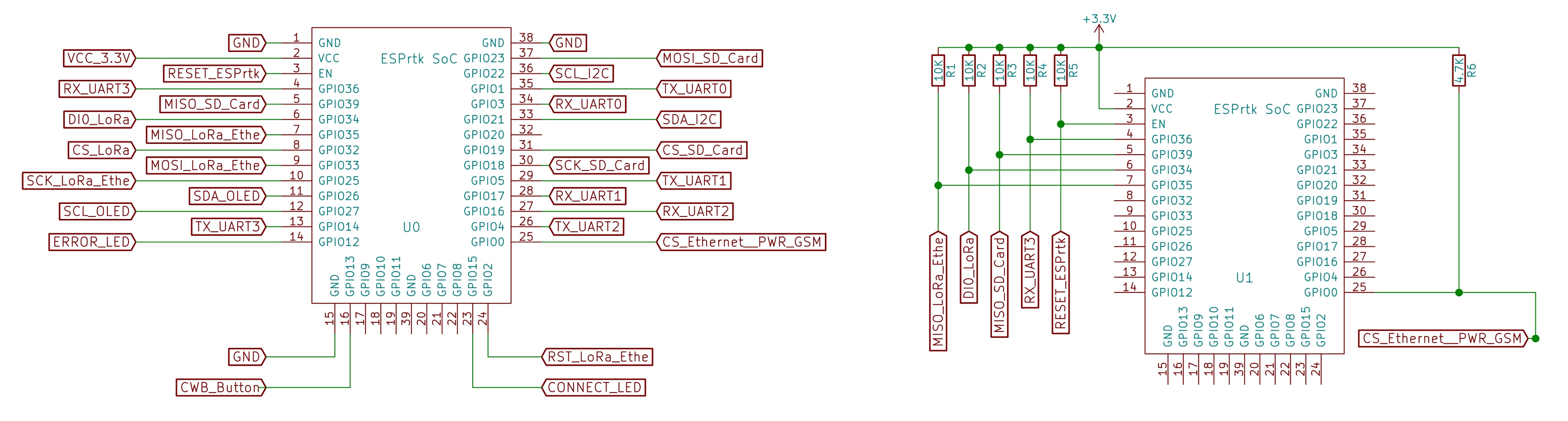
The above configuration will correspond to the diagram below:
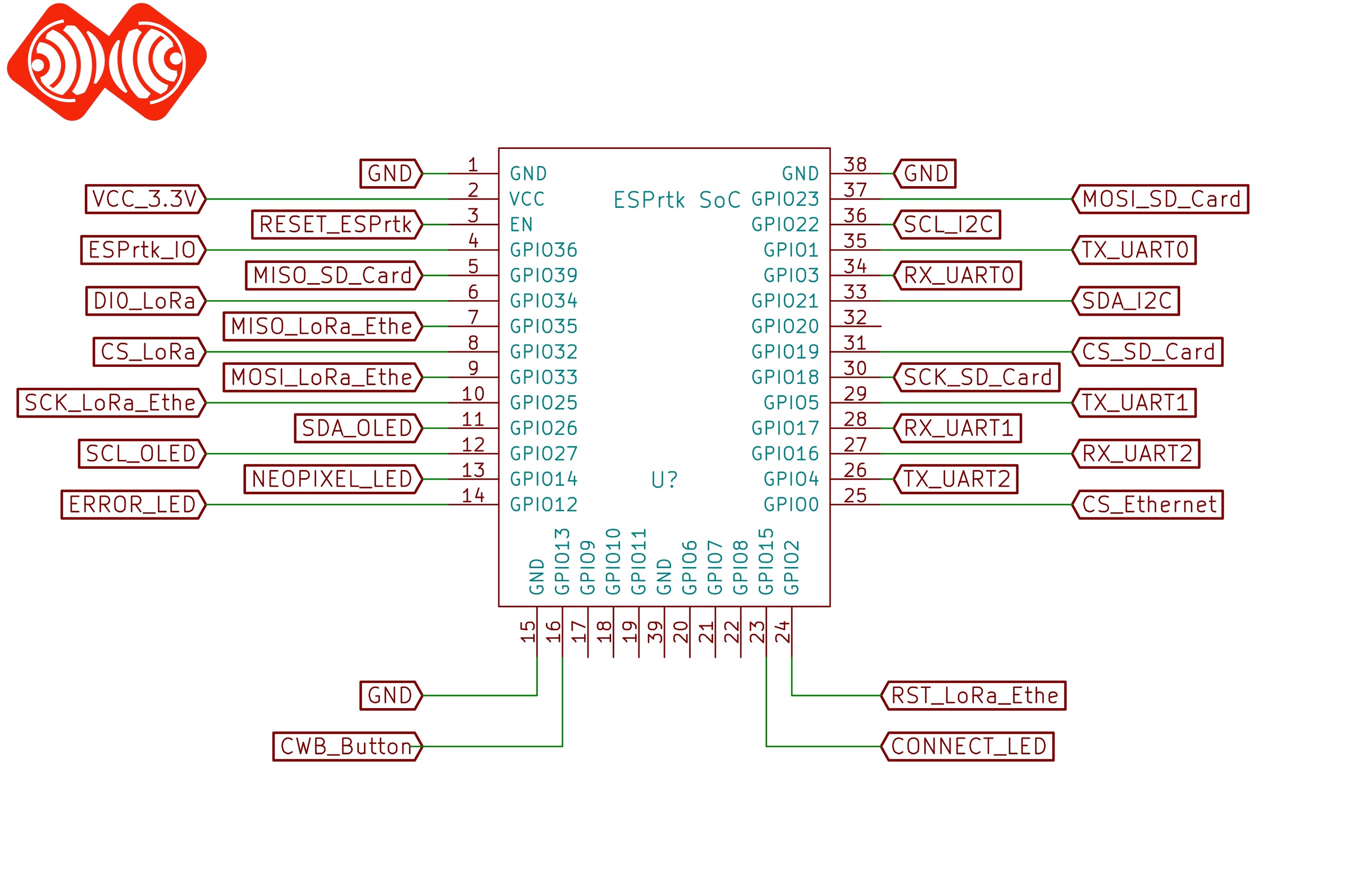
Please read ESPrtk datasheet for detail information about pinout on ESPrtk.
Application .
Besides helping make PCB design more flexible, this feature allows ESPrtk to be compatible on all hardware boards with different pinout designs.
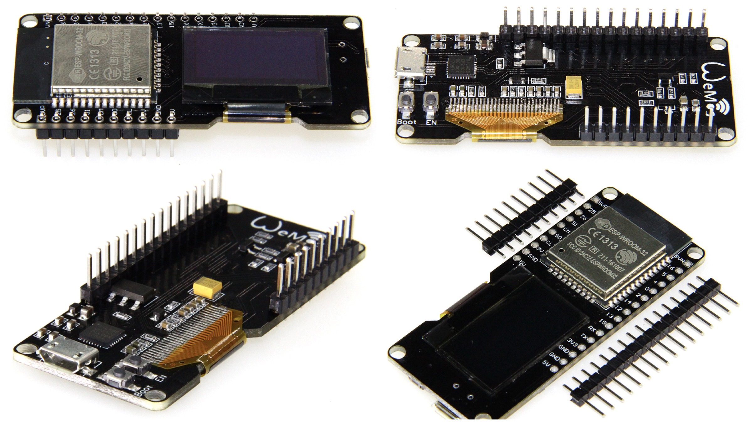
For example #1: WEMOS / Lolin ESP32 OLED board.
This module is integrated OLED LCD on GPIO5 (SDA_2) and GPIO4 (SCL_2) on board ( ESPrtk also supports OLED display ).
However, by default pin GPIO5 and GPIO4 on ESP32 are TX_UART1 and TX_UART2 of ESPrtk (see default JSON above) so we will swap the configuration on 6 pin, specifically:
- SCL_OLED : from 27 to 4
- SDA_OLED : from 26 to 5
- TX_UART2 : from 4 to 25
- TX_UART1 : from 5 to 26
- RX_UART1 : from 17 to 36
- RX_UART3 : from 36 to 17
And other pins remain the same as default.
The JSON code should be :
(copy all text in box)
The above configuration will correspond to the board below:
Connect with some componant as ESPrtk standard :
Then , you can connect it to the GNSS RTK modules here:
Connect ESPrtk with RTK Receiver and some other modules.
Note : this board only has 23 GPio Pin , so we cannot add SPI and I2C pin on it , that mean Ethernet and SD Card cannot use on this board !
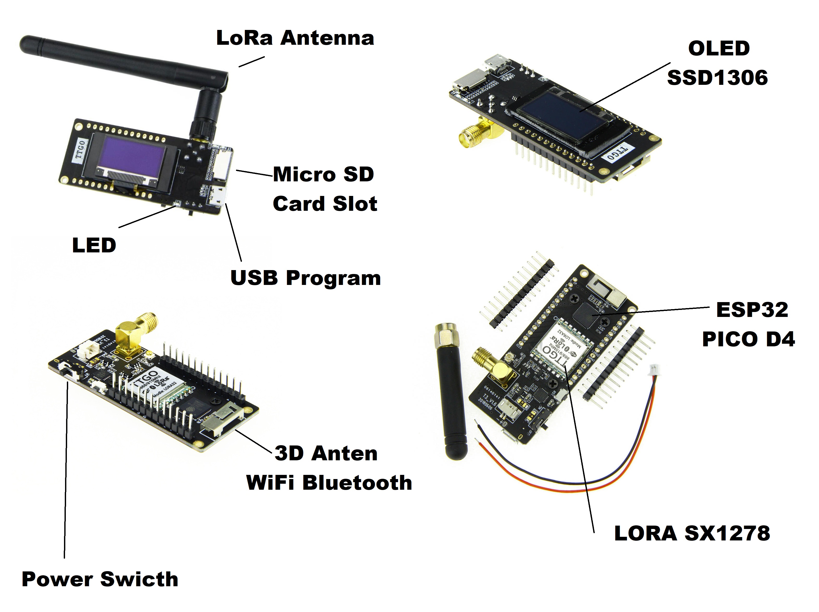
For example #2: LILYGO® TTGO LoRa32 V2.1 ESP32 433 MHz / 868 MHz / 915 MHz OLED 0.96 Inch SD Card Bluetooth WIFI Mô-đun SMA IP5306 + Custom Pinmap.
The JSON code should be :
(copy all text in box)
The above configuration will correspond to the board below:
Then , you can connect it to the GNSS RTK modules here:
Connect ESPrtk with RTK Receiver and some other modules.
- Make sure you changed Type CHIP ESP32 PICO before using. Go to http://192.168.4.1/system. , Then choose type CHIP ESP32 is ESP32 PICO D4 -> Press Save.
- We cannot using CONNECT_LED and NEOPIXEL_LED on this board !
- An additional piece of aluminum heatsink should be placed on CHIP ESP32 PICO to avoid temperature issues.
- Most GPIO pins (5/18/19/23/26/27) for SPI-LoRa are not connect to external output pins , if you plan to test Ethernet on this board, you need to connect the SPI-Ethernet interface directly with the pins on the LoRa module.
- The CWB Button now change from GPIO13 to GPIO36.
- You should also know: On this board, 2 pins GPIO04 / GPIO12 (for TX_UART1 / 2) are also connected to 2 Data2 / Data3 pins of the SD card slot. In fact, ESPrtk never uses these two Data2 / Data3 pins of a memory card.
Exceptions .
ESPrtk supports changing all output pins. However, not all configurations are accepted.
-Some GPio pins of ESP32 cannot be used for ESPrtk if it does not fully support. See table below
| GPio (ESP32) | …map to ESPrtk ( Input ) | .. map to ESPrtk ( Output ) |
| Input-Output | Yes | Yes |
| Input Only | Yes | No |
| Output Only | No | Yes |
Sometime the configuration is successfully saved (passes the Logic test) but ESPrtk will fail or not work properly, this depends on how the user configures and how ESP32 work with that configuration.
So users need to know the limitations of output pin on ESP32. Below is a brief summary ( see detail tutorial here https://randomnerdtutorials.com/esp32-pinout-reference-gpios/ )
| GPIO (ESP32) | Input | Output | Notes |
| 0 | pulled up | OK | outputs PWM signal at boot |
| 1 | TX pin | OK | debug output at boot |
| 2 | OK | OK | connected to on-board LED |
| 3 | OK | RX pin | HIGH at boot |
| 4 | OK | OK | |
| 5 | OK | OK | outputs PWM signal at boot |
| 6 | x | x | connected to the integrated SPI flash |
| 7 | x | x | connected to the integrated SPI flash |
| 8 | x | x | connected to the integrated SPI flash |
| 9 | x | x | connected to the integrated SPI flash |
| 10 | x | x | connected to the integrated SPI flash |
| 11 | x | x | connected to the integrated SPI flash |
| 12 | OK | OK | boot fail if pulled high |
| 13 | OK | OK | |
| 14 | OK | OK | outputs PWM signal at boot |
| 15 | OK | OK | outputs PWM signal at boot |
| 16 | OK | OK | |
| 17 | OK | OK | |
| 18 | OK | OK | |
| 19 | OK | OK | |
| 21 | OK | OK | |
| 22 | OK | OK | |
| 23 | OK | OK | |
| 25 | OK | OK | |
| 26 | OK | OK | |
| 27 | OK | OK | |
| 32 | OK | OK | |
| 33 | OK | OK | |
| 34 | OK | input only | |
| 35 | OK | input only | |
| 36 | OK | input only | |
| 39 | OK | input only |
Continue reading for a more detail and in-depth analysis of the ESP32 GPIOs and its functions.
Input only pins
GPIOs 34 to 39 are GPIs – input only pins. These pins don’t have internal pull-ups or pull-down resistors. They can’t be used as outputs, so use these pins only as inputs:
- GPIO 34
- GPIO 35
- GPIO 36
- GPIO 39