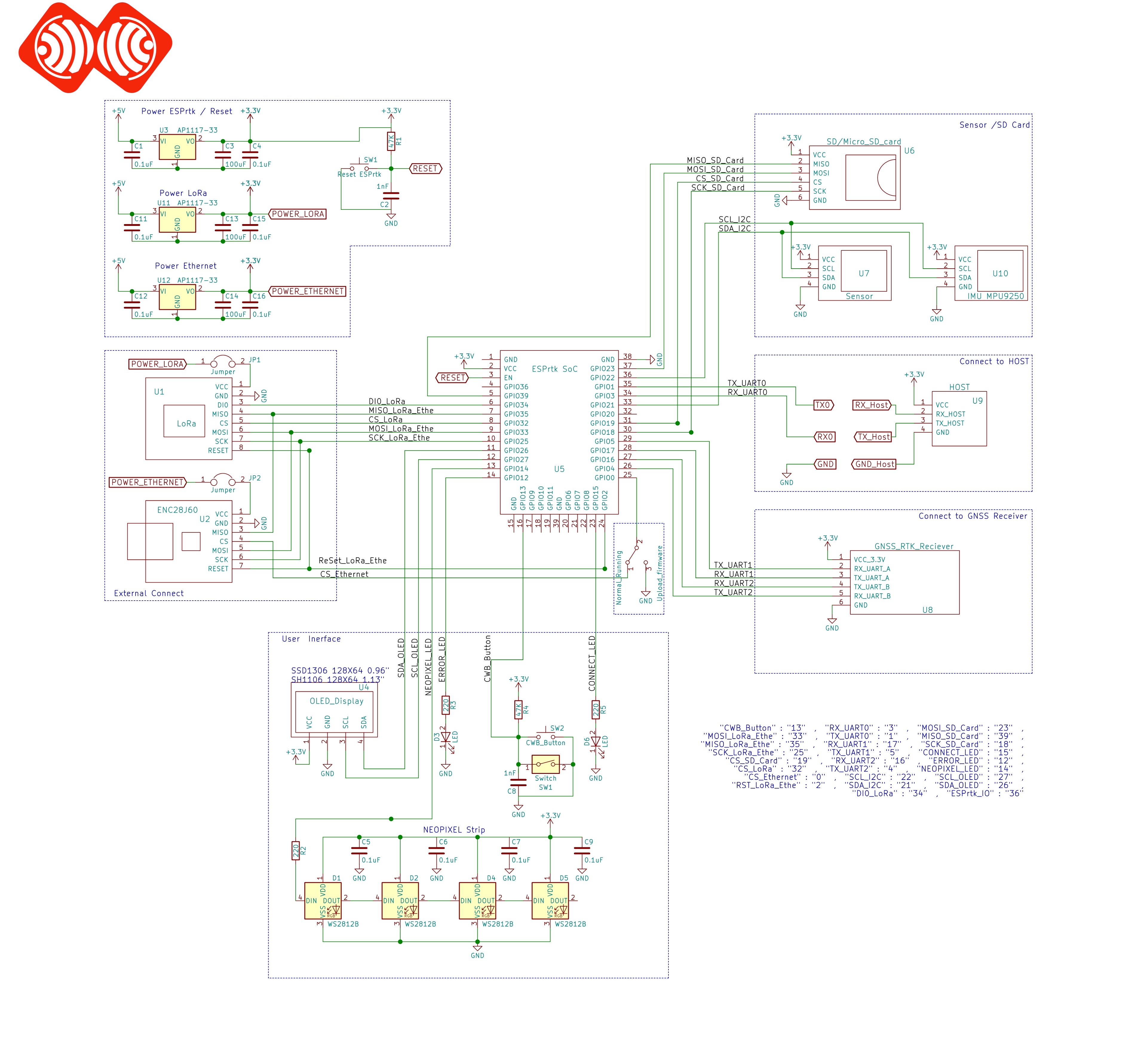
Here is some circuit diagram.
Connection model for:
- MQTT BASE – ROVER.
- NTRIP BASE – ROVER.
(If the router supports wifi connection, the connection between ESPrtk and the ENC28J60 ethernet module is not required.)

Connection model for:
- WIFI TCP BASE – ROVER.
- WIFI UDP BASE – ROVER.
- BLUETOOTH BRIDGE BASE – ROVER.

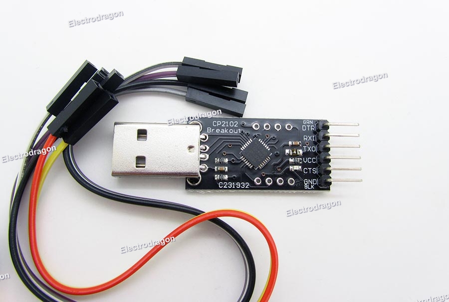
USB to UART module.
If your ESP32 board does not support USB port, you need to buy additional USB to UART module, like CP2102-USB-TTL-UART-Module-V2 as below , it will help you upload firmware to ESP32 and also helpful to use it to configure Ublox (or Navspark) module .
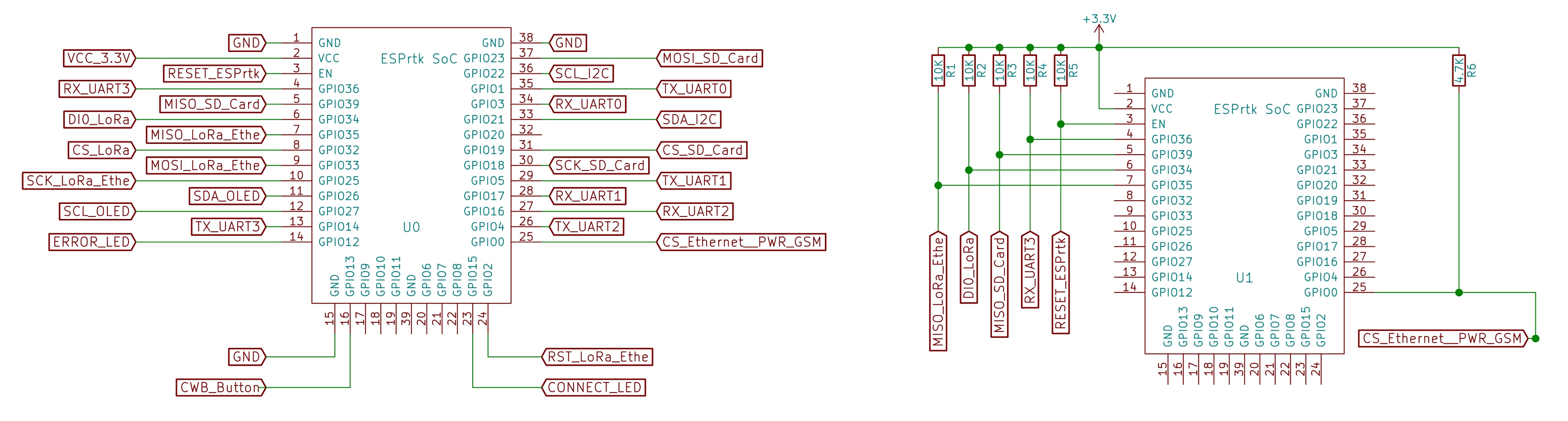
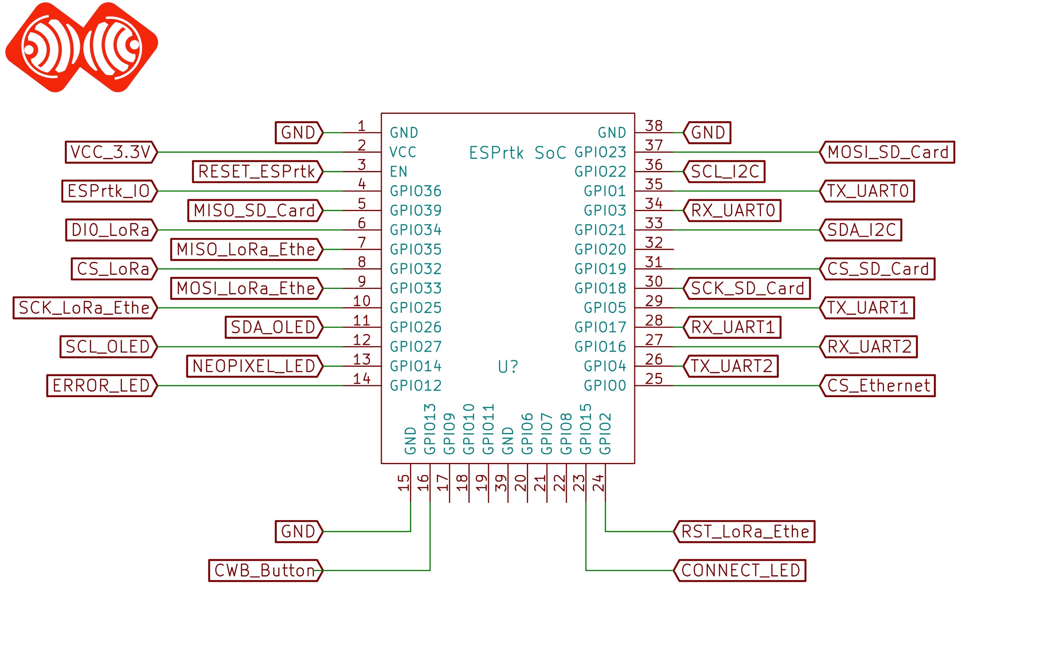
ESPrtk SoC pinout.
Please read ESPrtk datasheet for detail information about pinout on ESPrtk.
Connect ESPrtk simpleRTK2B from ardusimple – ZED-F9P Ublox .

Now connect them.

IOREF: this is an input that will define the voltage levels of the next pins. If you input 1.8V, the next pins will be 1.8V level. It supports from 1.2V to 5.5V.
If your are connecting your own hardware to UART1 or UART2, it is mandatory to connect IOREF pin to the voltage required by your hardware, otherwise you may experience problems.
See more here : https://www.ardusimple.com/simplertk2b-hookup-guide/
Connect ESPrtk with Drotek TinyRTK Board – NEO-M8P-2 .

Now connect them.

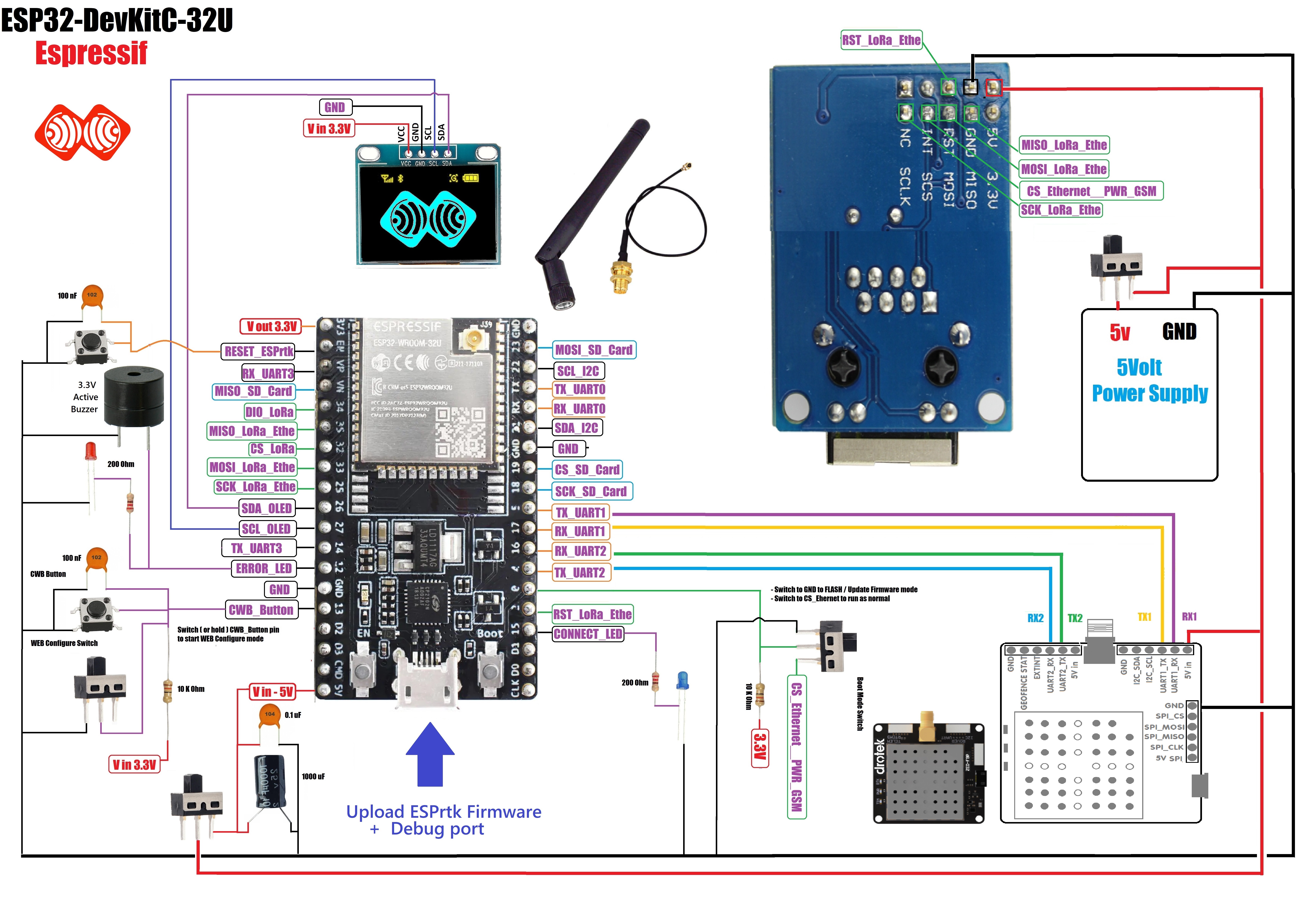
Connect ESPrtk with Drotek F9P Board – F9P-ZED-Ublox .


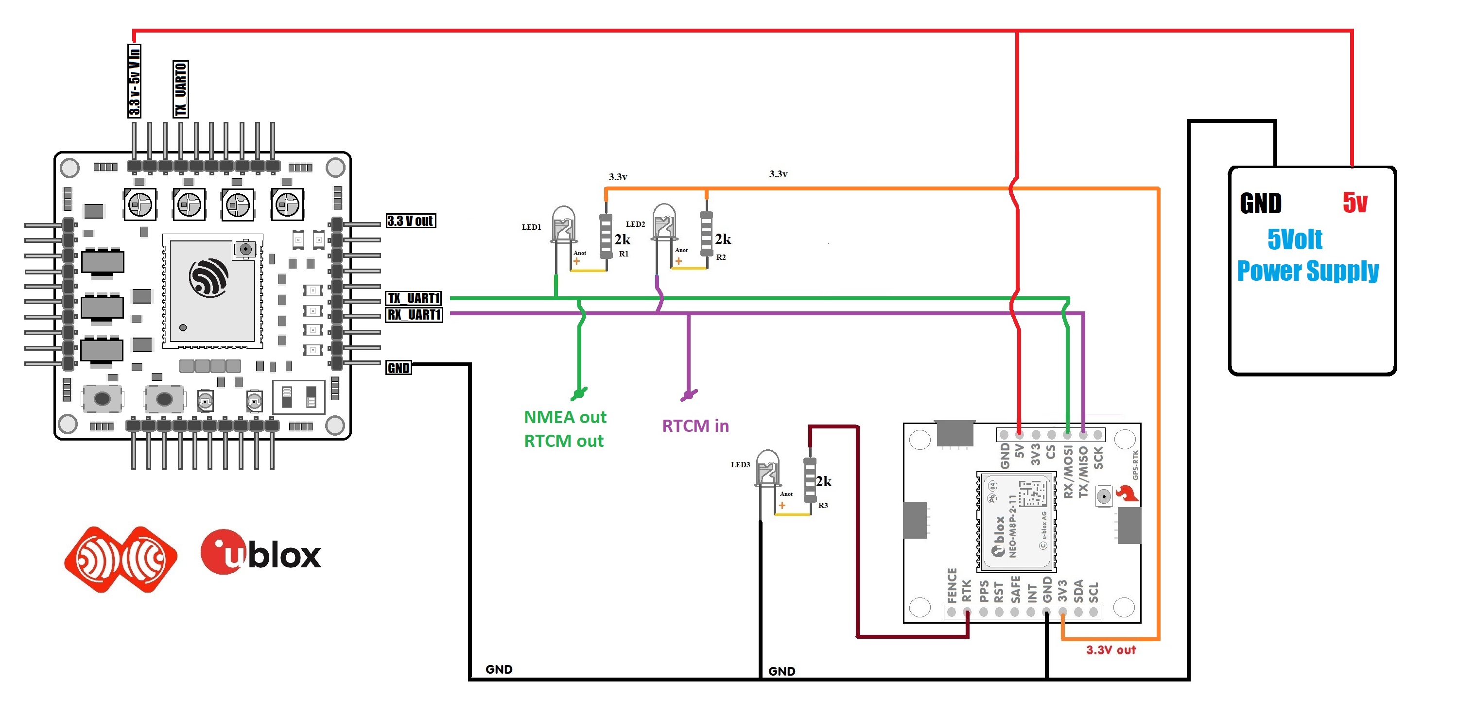
Connect ESPrtk with SparkFun GPS-RTK Board – NEO-M8P-2 (Qwiic) .
Ublox M8P-2 run at 3.3Volt, but Sparkfun module support 5v to 3.3v converter IC.

Now connect them.
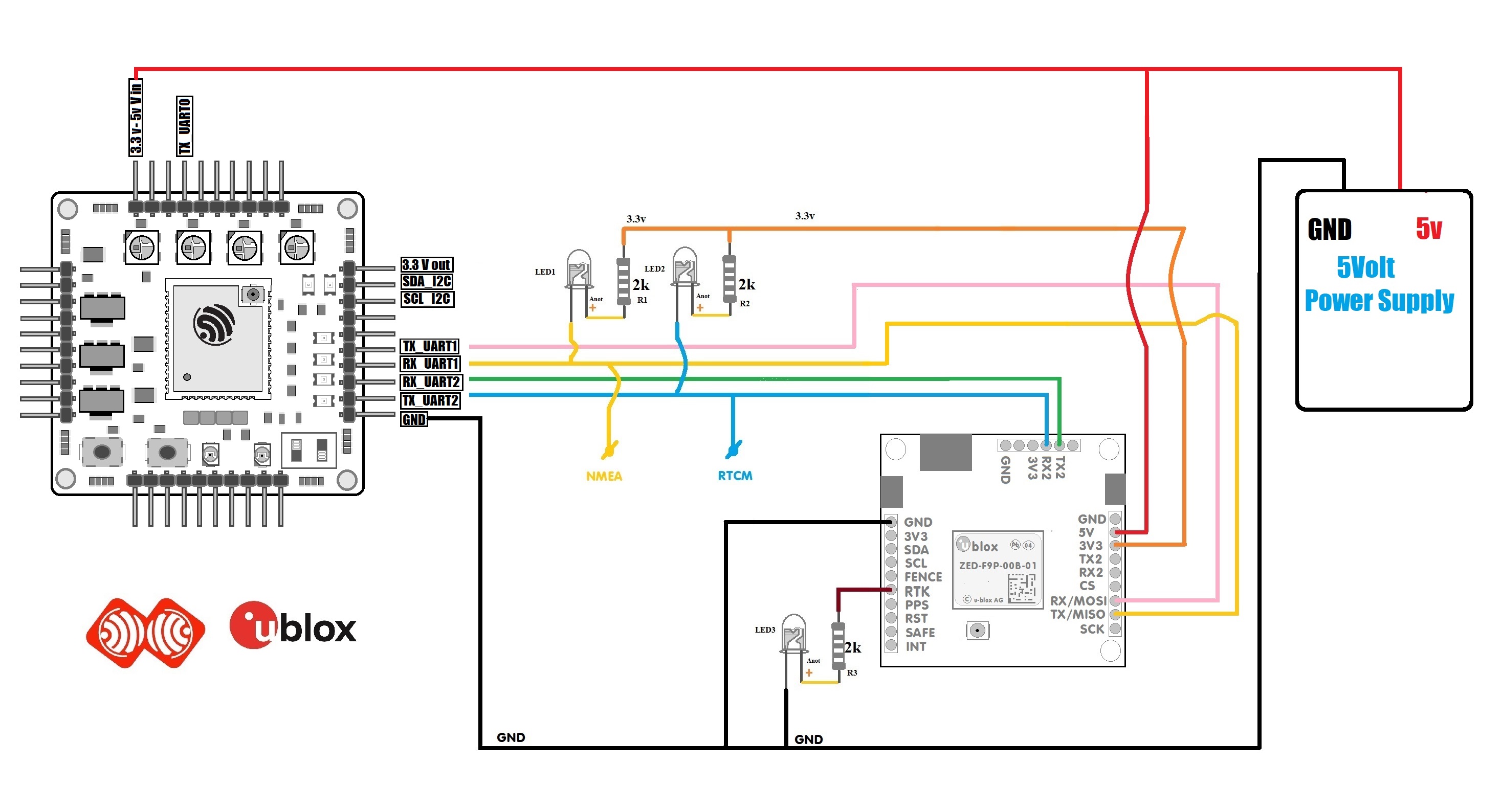
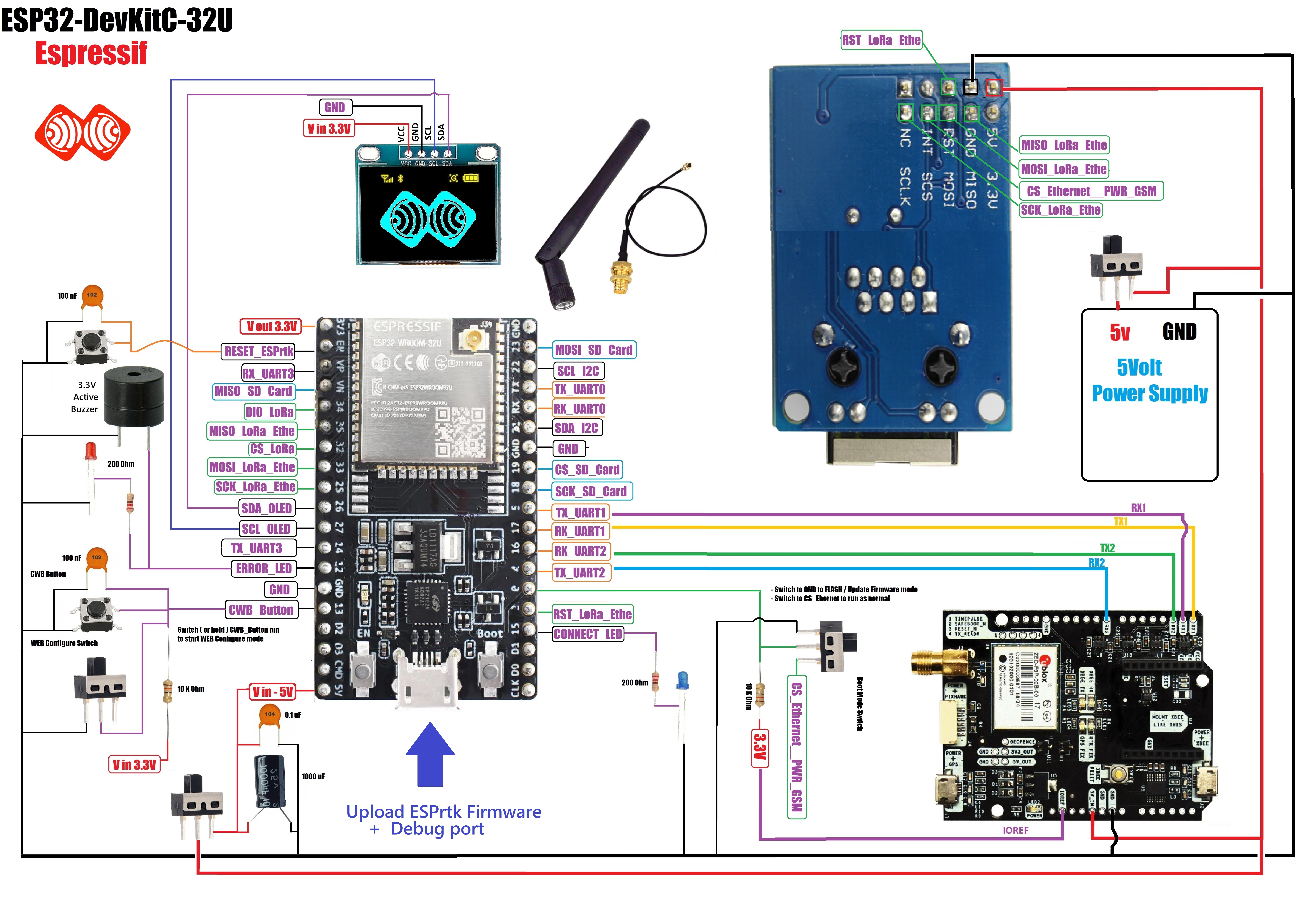
Connect ESPrtk with SparkFun GPS-RTK Board –ZED F9P (Qwiic) .
Ublox ZED F9P run at 3.3Volt, but Sparkfun module support 5v to 3.3v converter IC.
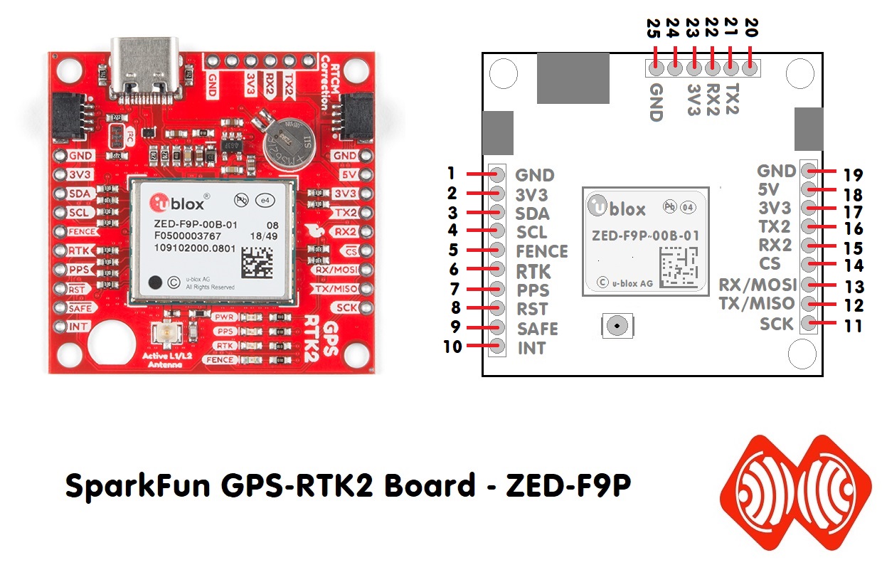
Now connect them.
Connect ESPrtk with Navspark NS-HP-BD or NS-HP-GL from Skytraq.
NS-HP-BD or NS-HP-GL work on 3.3volt supply. We need 5v to 3.3v converter module to power it.

Now connect them.

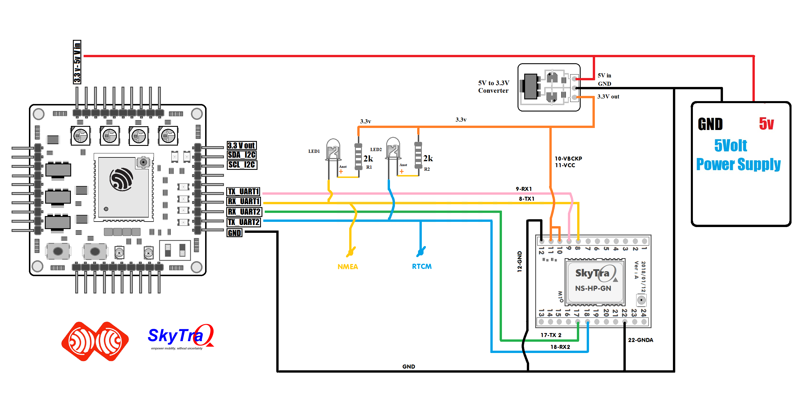
Connect ESPrtk with Navspark NS-HP-GN from Skytraq.
NS-HP-GN work on 3.3volt supply. We need 5v to 3.3v converter module to power it.

Now connect them.
(NS-HP-GN has not support STS pin ,But it is being considered for use on GPIO10 in future software updates.)
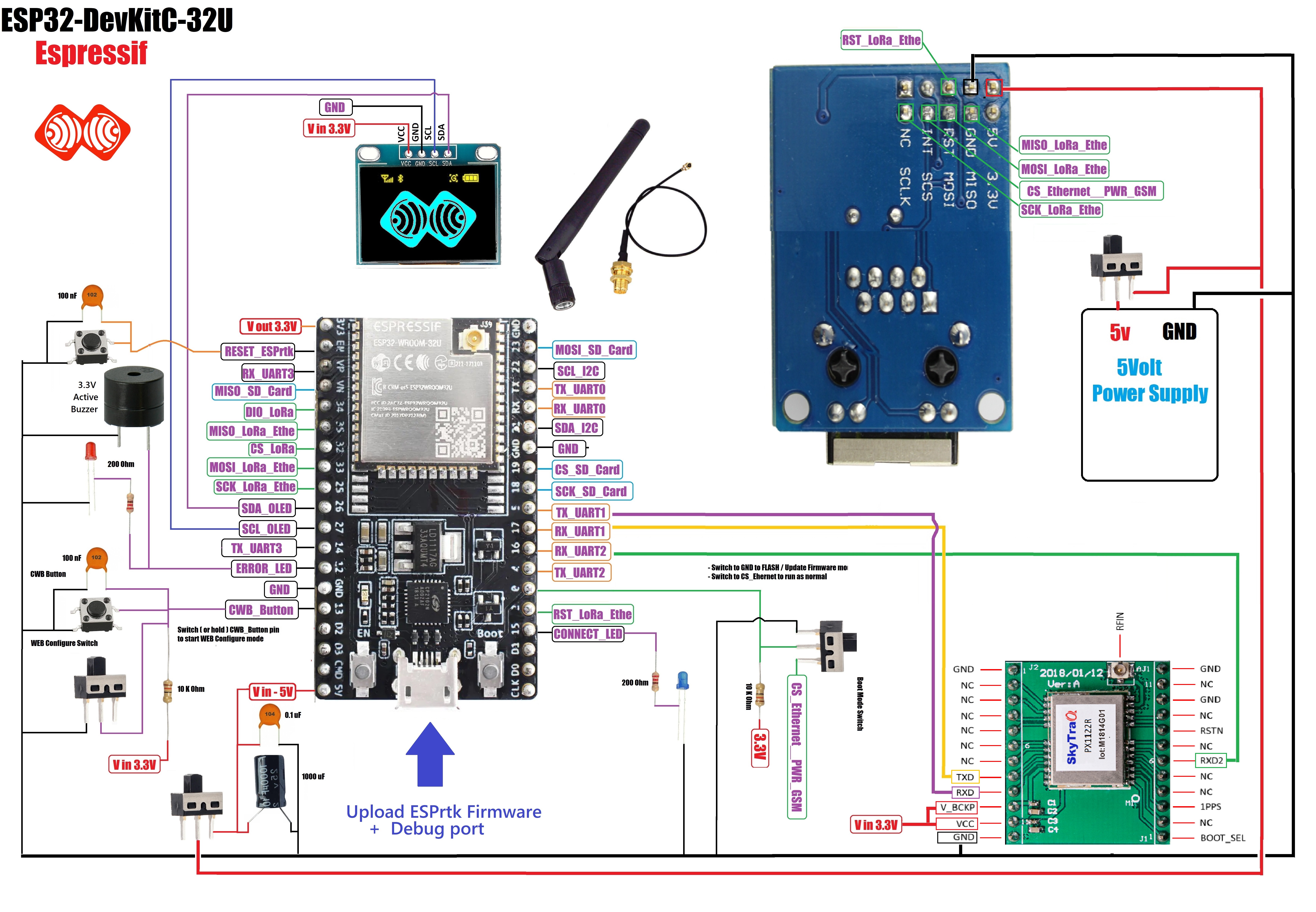
Connect ESPrtk with Navspark PX1122R from Skytraq.
NS-HP-GN work on 3.3volt supply. We need 5v to 3.3v converter module to power it.

Now connect them.
( TX2 pin of PX1122R has been removed, the RTCM sending function will be executed on the TXD port of PX1122R.)

Connect ESPrtk with W5500 Ethernet Module.

If the router does not support wifi connection, you can connect ESPrtk to the W5500 ethernet Module.

Connect ESPrtk with W5100 ETHERNET MODULE.

Connect ESPrtk with ENC28J60 ETHERNET MODULE.

If the router does not support wifi connection, you can connect ESPrtk to the ENC28J60 ethernet module.


Connect ESPrtk with SD Card

Connect ESPrtk with Sparkfun SD Card Slot module.


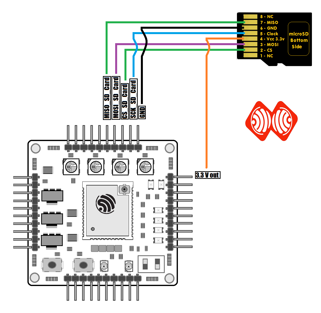
Connect ESPrtk with Other SD Card Slot module.

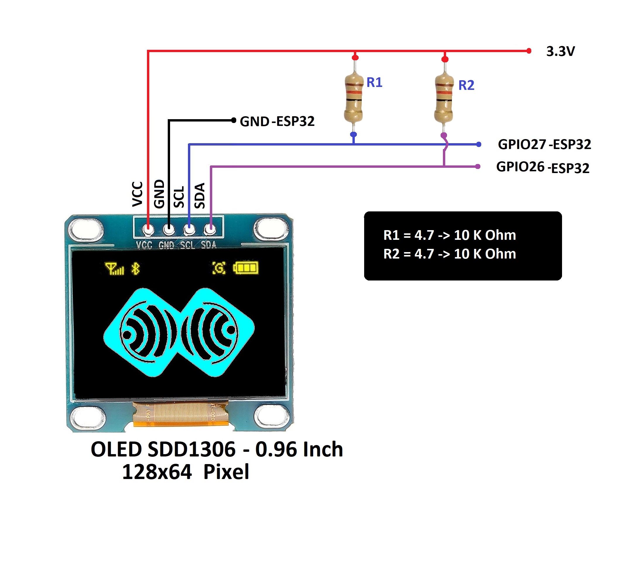
Connect ESPrtk with OLED SSD1306 LCD 0.96 inch.
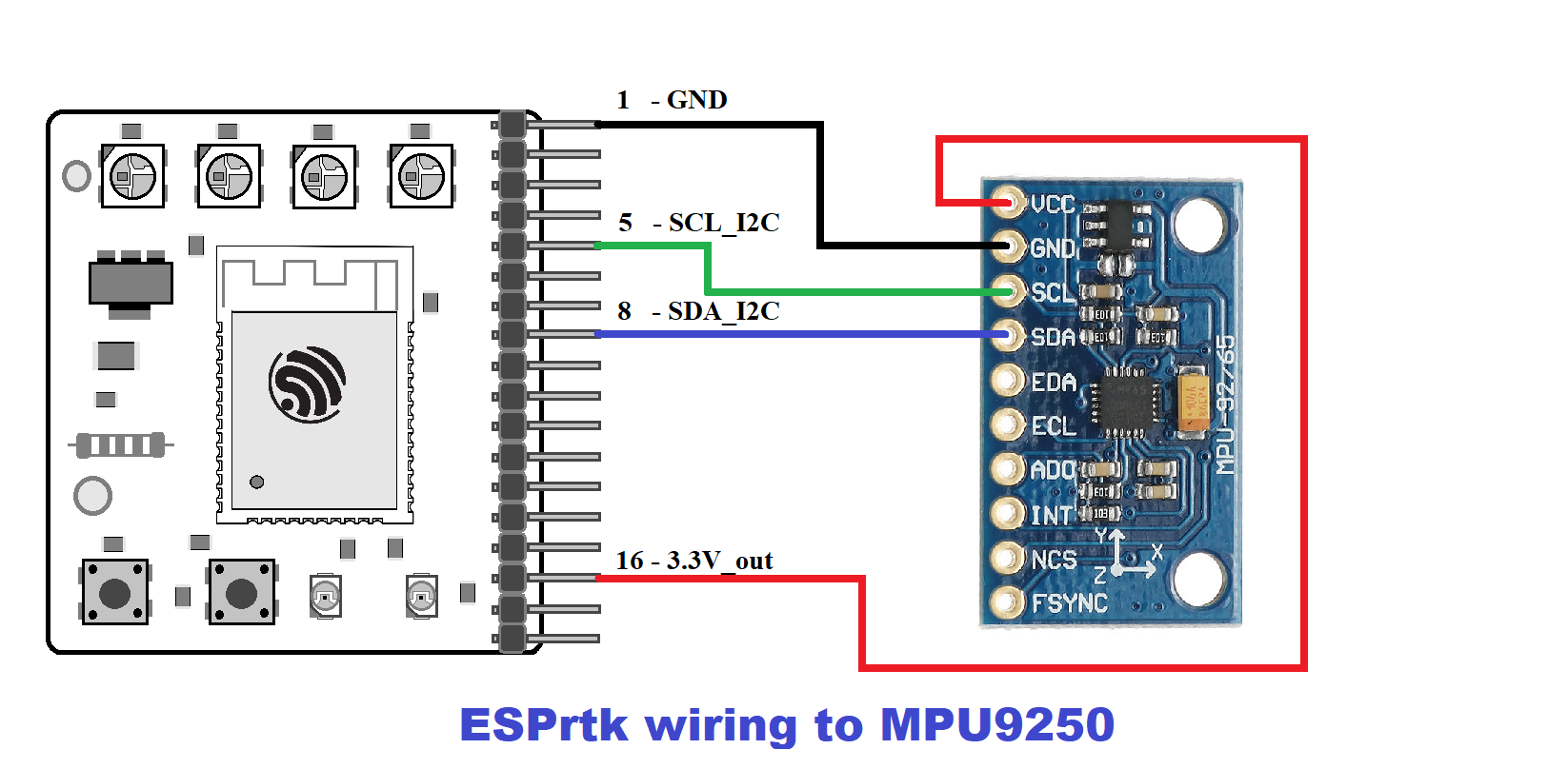
Connect ESPrtk with MPU9250 Sensor.

Connect ESPrtk LoRa SX1276 SX1277 SX1278 SX1279.
LoraSX1278- 20dBm sx1278 LORA Module 2Km

Lora1278F30 - 30dBm sx1278 LORA Module small size 6Km to 8Km 433MHz high power 1W long range RF transceiver


Connect ESPrtk to GSM/Cellular Module

Connect ESPrtk with NB-IOT, LTE-M, EGPRS Arduino SHIELD QG96 (QUECTEL BG96 MA CHIP) GSM/Cellular Module.


Connect ESPrtk with MIKROE LTE IoT 2 Click (QUECTEL BG96 MA CHIP) GSM/Cellular Module.

Connect ESPrtk with Quectel BG96 Red GSM/Cellular Module. (QUECTEL BG96 MA CHIP)

Connect ESPrtk with Quectel BG96 RAK GSM/Cellular Module. (QUECTEL BG96 MA CHIP)

Connect ESPrtk with Simcom SIM800L-800C GSM/Cellular Module.


Connect ESPrtk with Simcom SIM800L-800C V2 EVB GSM/Cellular Module.

Connect ESPrtk with Simcom SIM868 Green GSM/Cellular Module.


Connect ESPrtk with Simcom SIM868 Red GSM/Cellular Module.

Connect ESPrtk with Simcom SIM5320E Green GSM/Cellular Module.


Connect ESPrtk with Simcom SIM5320E Adafruit GSM/Cellular Module.

Connect ESPrtk with Simcom SIM7600E GSM/Cellular Module.

Connect ESPrtk with Ublox Sara R410M Sparkfun GSM/Cellular Module.

Connect ESPrtk with Ublox Sara R410M GSM/Cellular Module.

Connect ESPrtk with Ublox Sara U210 GSM/Cellular Module.

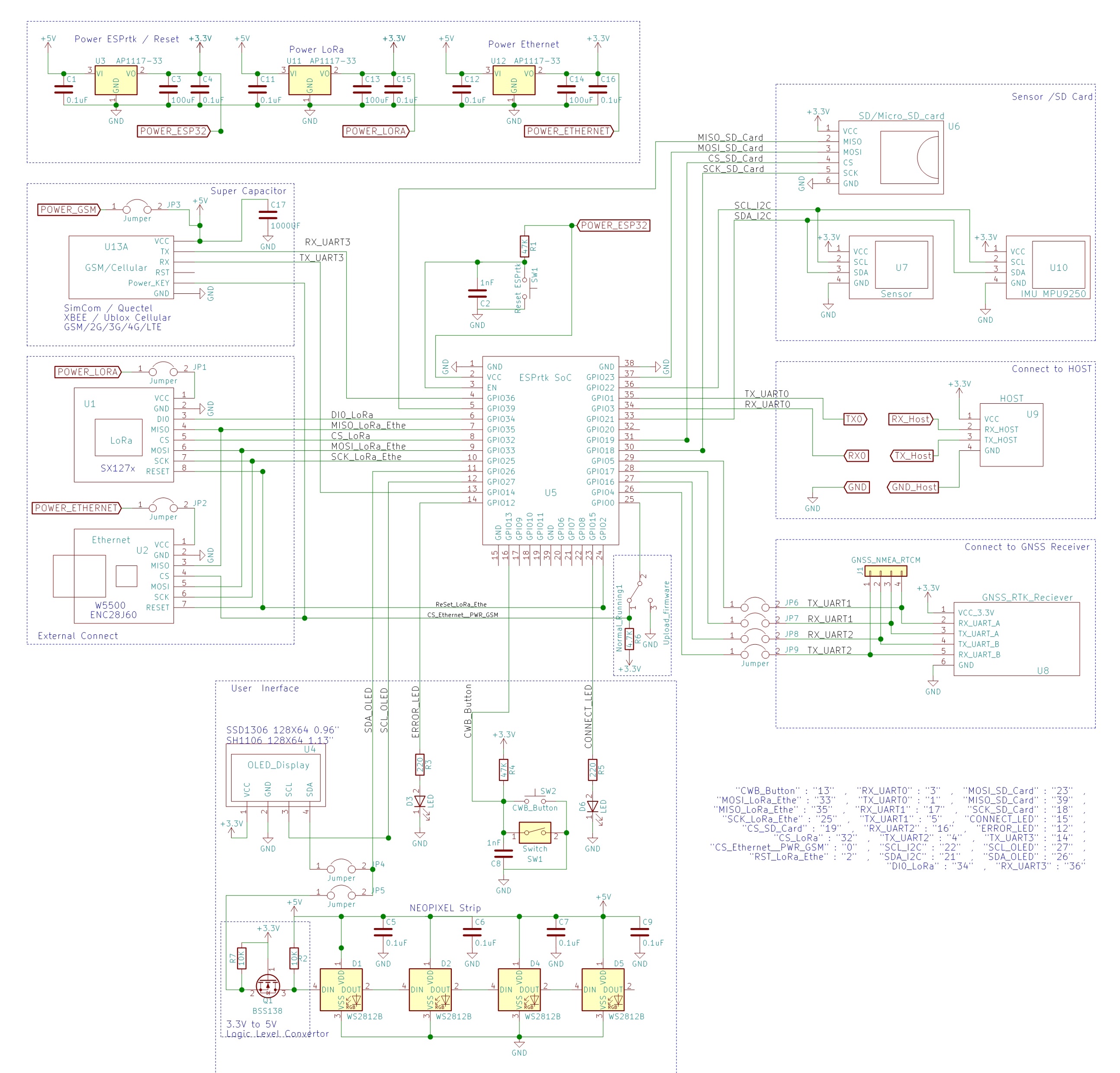
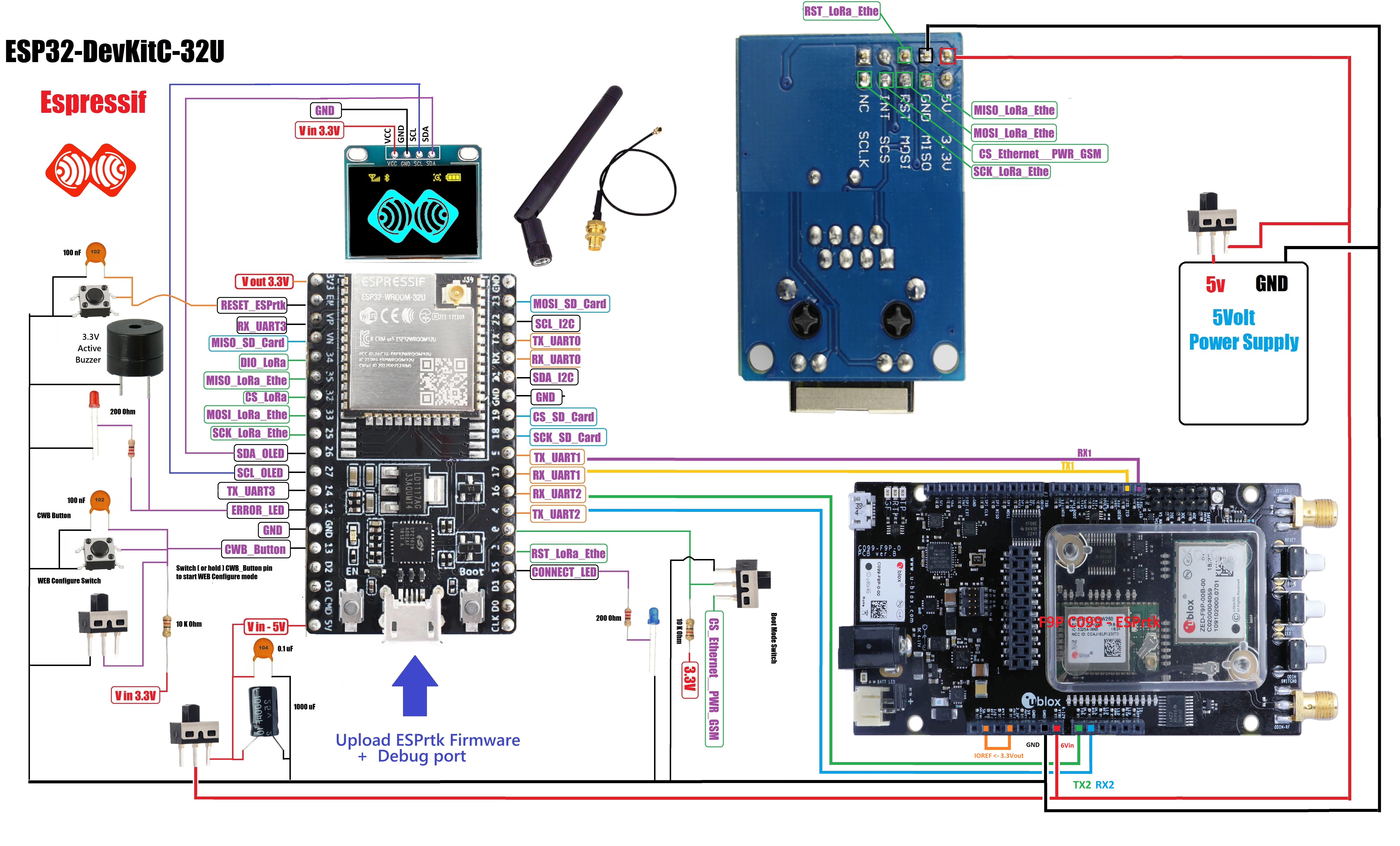
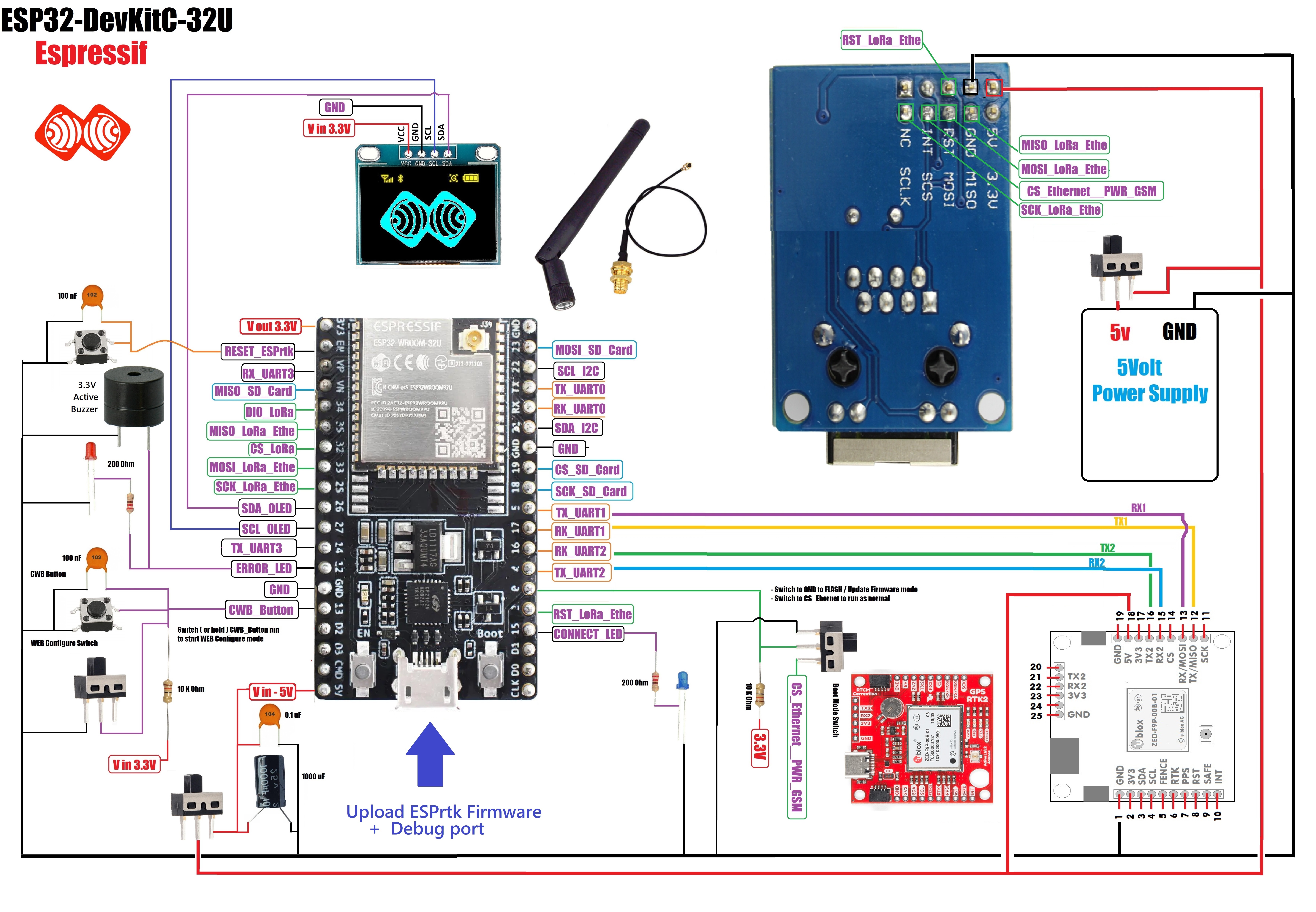
Full connection.

Example :
- App Build : NTRIP/MQTT RTK BaseStation+Rover
- ESP32 : ESP32 DEV KIT C Espressif (ESP32_WROOM_32U CHIP)
- Ethernet : W5500
- RTK GNSS: F9P
- Display: OLED SSD1306
- Power supply: 5V 2.5A Adapter
- Other: LED , Button, Switch , 2.4Ghz WiFi Antenna , GNSS RTK Antenna, RJ45 Etheret cable, Micro USB Cable , 3.3V Active Buzzer , ...
Circuit diagram as below .

Connect ESPrtk with C099-F9P GPS-RTK Board – UBLOX DEV BOARD .
For NTRIP RTK Basestation application - PX1122R/F9P + ESP32 + TRIMBLE, TOPCON, John Deere
Ublox F9P run at 3.3Volt, but Sparkfun module support 5v to 3.3v converter IC.
For users who prefer simplicity and minimize all connections or for quick test purposes. Wireless internet connection using WIFI on ESP32 will be suitable.

- PX1122R/PX1172R - Navspark (Fullsize)
- F9P - Drotek (Fullsize)
- F9P - Ardusimple (Fullsize)
- F9P - Sparkfun (Fullsize)
- F9P - C099-F9P UBLOX (Fullsize)
For RTK Basestation applications with up to several months or years of continuous uptime, we always recommend users to use the W5500 Ethernet module for their systems to ensure a stable 24-hour connection !.
In addition, it is possible to add 1 buzzer on the ERROR LED pin (3.3V Active Buzzer) and 1 small OLED module to be able to see the operating status, (connection status, error, flow rate, etc.) of the whole. system .
Here is some circuit diagram.
Connection model for:
- MQTT BASE – ROVER.
- NTRIP BASE – ROVER.
(If the router supports wifi connection, the connection between ESPrtk and the ENC28J60 ethernet module is not required.)
Connection model for:
- WIFI TCP BASE – ROVER.
- WIFI UDP BASE – ROVER.
- BLUETOOTH BRIDGE BASE – ROVER.
USB to UART module.
If your ESP32 board does not support USB port, you need to buy additional USB to UART module, like CP2102-USB-TTL-UART-Module-V2 as below , it will help you upload firmware to ESP32 and also helpful to use it to configure Ublox (or Navspark) module .
ESPrtk SoC pinout.
Please read ESPrtk datasheet for detail information about pinout on ESPrtk.
Connect ESPrtk simpleRTK2B from ardusimple – ZED-F9P Ublox .
Now connect them.
IOREF: this is an input that will define the voltage levels of the next pins. If you input 1.8V, the next pins will be 1.8V level. It supports from 1.2V to 5.5V.
If your are connecting your own hardware to UART1 or UART2, it is mandatory to connect IOREF pin to the voltage required by your hardware, otherwise you may experience problems.
See more here : https://www.ardusimple.com/simplertk2b-hookup-guide/
Connect ESPrtk with Drotek TinyRTK Board – NEO-M8P-2 .
Now connect them.
Connect ESPrtk with Drotek F9P Board – F9P-ZED-Ublox .
Connect ESPrtk with SparkFun GPS-RTK Board – NEO-M8P-2 (Qwiic) .
Ublox M8P-2 run at 3.3Volt, but Sparkfun module support 5v to 3.3v converter IC.
Now connect them.
Connect ESPrtk with SparkFun GPS-RTK Board –ZED F9P (Qwiic) .
Ublox ZED F9P run at 3.3Volt, but Sparkfun module support 5v to 3.3v converter IC.
Now connect them.
Connect ESPrtk with Navspark NS-HP-BD or NS-HP-GL from Skytra.
NS-HP-BD or NS-HP-GL work on 3.3volt supply. We need 5v to 3.3v converter module to power it.
Now connect them.
Connect ESPrtk with Navspark NS-HP-GN from Skytra.
NS-HP-GN work on 3.3volt supply. We need 5v to 3.3v converter module to power it.
Now connect them.
(NS-HP-GN has not support STS pin ,But it is being considered for use on GPIO10 in future software updates.)
Connect ESPrtk with ENC28J60 ETHERNET MODULE.
If the router does not support wifi connection, you can connect ESPrtk to the ENC28J60 ethernet module.
Connect ESPrtk with SD Card
Connect ESPrtk with Sparkfun SD Card Slot module.
Connect ESPrtk with Other SD Card Slot module.
Connect ESPrtk with OLED SSD1306 LCD 0.96 inch.
Connect ESPrtk with MPU9250 Sensor.
Connect ESPrtk LoRa SX1276 SX1277 SX1278 SX1279.
LoraSX1278- 20dBm sx1278 LORA Module 2Km
Lora1278F30 - 30dBm sx1278 LORA Module small size 6Km to 8Km 433MHz high power 1W long range RF transceiver
Full connection.

Here is some circuit diagram.
Connection model for:
- MQTT BASE – ROVER.
- NTRIP BASE – ROVER.
(If the router supports wifi connection, the connection between ESPrtk and the ENC28J60 ethernet module is not required.)
Connection model for:
- WIFI TCP BASE – ROVER.
- WIFI UDP BASE – ROVER.
- BLUETOOTH BRIDGE BASE – ROVER.
USB to UART module.
If your ESP32 board does not support USB port, you need to buy additional USB to UART module, like CP2102-USB-TTL-UART-Module-V2 as below , it will help you upload firmware to ESP32 and also helpful to use it to configure Ublox (or Navspark) module .
Connect ESPrtk simpleRTK2B from ardusimple – ZED-F9P Ublox .
Now connect them.

IOREF: this is an input that will define the voltage levels of the next pins. If you input 1.8V, the next pins will be 1.8V level. It supports from 1.2V to 5.5V.
If your are connecting your own hardware to UART1 or UART2, it is mandatory to connect IOREF pin to the voltage required by your hardware, otherwise you may experience problems.
See more here : https://www.ardusimple.com/simplertk2b-hookup-guide/
Connect ESPrtk with Drotek TinyRTK Board – NEO-M8P-2 .
Now connect them.

Connect ESPrtk with Drotek F9P Board – F9P-ZED-Ublox .

Connect ESPrtk with SparkFun GPS-RTK Board – NEO-M8P-2 (Qwiic) .
Ublox M8P-2 run at 3.3Volt, but Sparkfun module support 5v to 3.3v converter IC.
Now connect them.

Connect ESPrtk with SparkFun GPS-RTK Board –ZED F9P (Qwiic) .
Ublox ZED F9P run at 3.3Volt, but Sparkfun module support 5v to 3.3v converter IC.
Now connect them.

Connect ESPrtk with Navspark NS-HP-BD or NS-HP-GL from Skytra.
NS-HP-BD or NS-HP-GL work on 3.3volt supply. We need 5v to 3.3v converter module to power it.
Now connect them.

Connect ESPrtk with Navspark NS-HP-GN from Skytra.
NS-HP-GN work on 3.3volt supply. We need 5v to 3.3v converter module to power it.
Now connect them.
(NS-HP-GN has not support STS pin ,But it is being considered for use on GPIO10 in future software updates.)

Connect ESPrtk with ENC28J60 ETHERNET MODULE.
If the router does not support wifi connection, you can connect ESPrtk to the ENC28J60 ethernet module.


Connect ESPrtk with SD Card

Connect ESPrtk with Sparkfun SD Card Slot module.

Connect ESPrtk with Other SD Card Slot module.

Connect ESPrtk with OLED SSD1306 LCD 0.96 inch.
Connect ESPrtk with MPU9250 Sensor.
