GNSS_VIEWER Introduce .
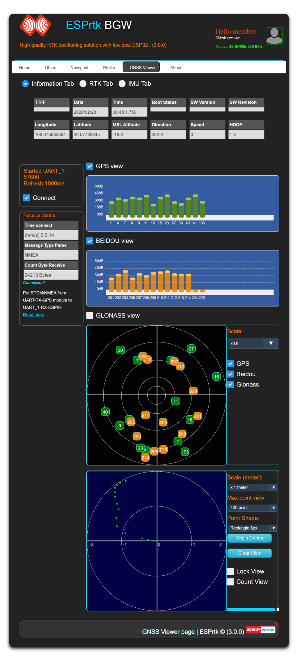
Message decoding tool NMEA / RTCM from GNSS positioning devices.
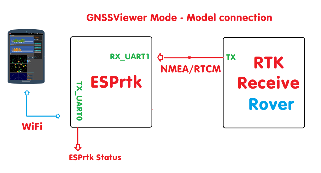
Connect the RX-UART1 port to the TX output of the GNSS device.
Select connection baudrate and screen update frequency then press connect.
For more detial about hardware connection, Click here.
Note: If the input is RTCM, ESPrtk 2.4.1 currently only recognizes RTCM 3.x but does not really resolve it because it is not fully supported yet.
If the input is NMEA, the following messages will be parse: RMC-GLL-GGA – GSA-ZDA-VTG-GSV.
SD CARD
On ESPrtk 3.9.8X, ESPrtk version 3.9.X supports storage of stream data on RX-UART-RTK port to SD card simultaneously with GNSS viewer.
You can also use this feature to check if the SD CARD is correctly connected to the ESPrtk or not !.
IMU_VIEWER Introduce .
This feature is available on version 2.7.5 or higher.
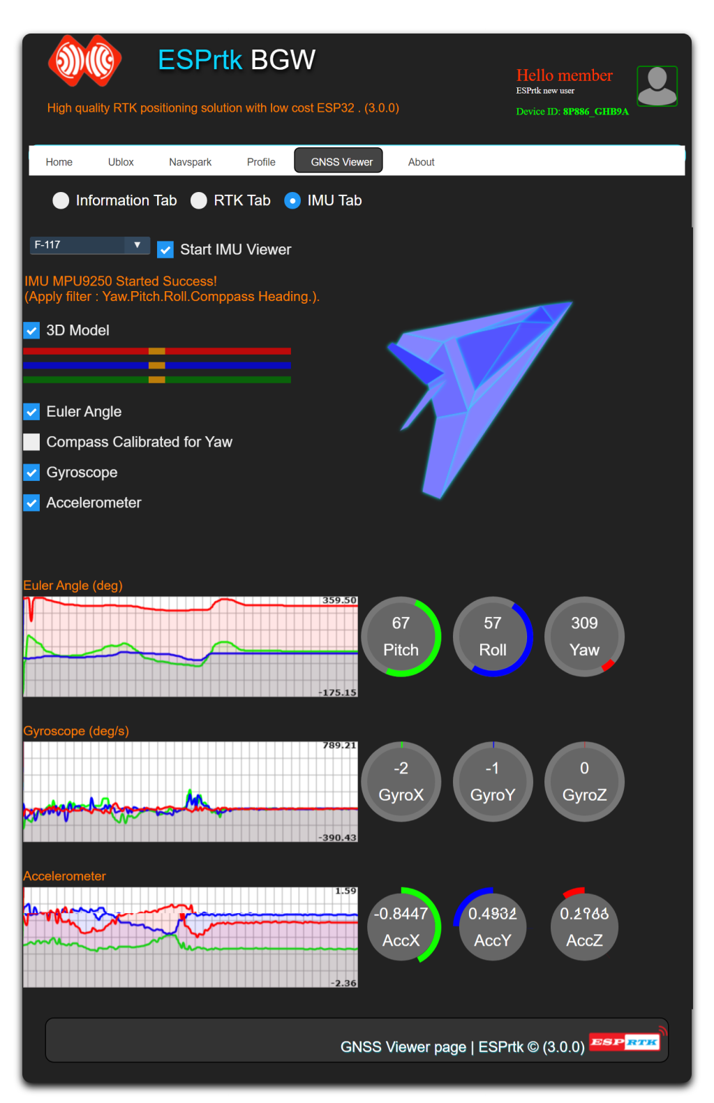
Read data from MPU9250 and display as real-time graph, value bar and 3D model.
Video demo :
Wiring MPU9250 to use with ESPrtk
See the circuit diagram here : Export IMU Data to TX_UART_0 port .
3D Model.
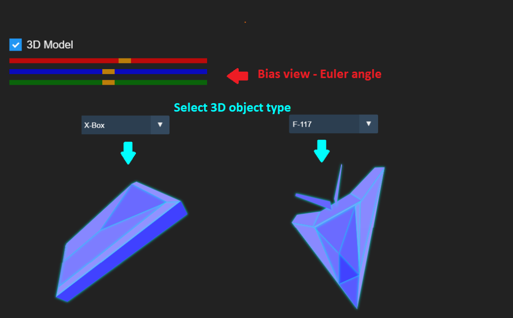
Draw a 3D object simulation with rotation angle taken from Pitch-Roll-Yaw -Compass heading data.
The Camera’s viewing angle can be changed by using the Bias Yaw-Pitch-Roll value bars. (Default all Bias set to 0).
Euler Angle.
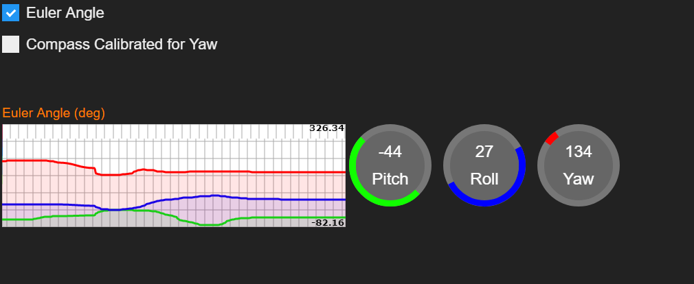
Display of 3 Euler angles: Yaw-Pitch-Roll.
Unit: degree.
Special :
The value of Yaw will drift after a long enough time even when the sensor is not moving or rotating.
Compass can be used as a Yaw value by selecting ‘Compass Calibrated for Yaw‘ mode.
In this way, the value of Yaw (in Euler Angle) and the rotation angle Z axis (in 3D Model) will be the compass value H (Magnetometer calibrated + Tilt compensation) or HF (Magnetometer calibrated + Tilt compensation +Kalman Filter) when the filter is applied.
However, before select this mode, make sure the compass has been calibrated by filling in the Transformation Matrix in ‘Profile -> IMU MPU9250’ tab.
To calibrate magnetometer on ESPrtk : IMU MPU9250 : Calibrate magnetometer on ESPrtk using Magneto1.2.
See more about H ,HF and Transformation Matrix here : Export IMU Data to TX_UART_0 port.
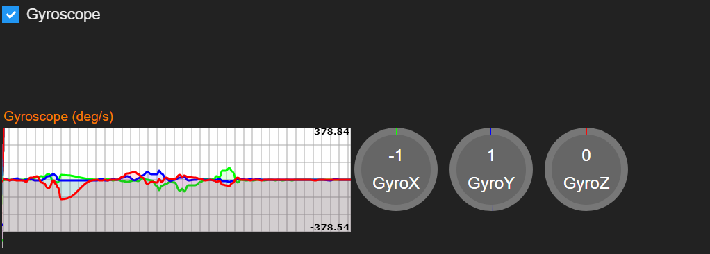
Gyroscope.
Display Gyro value on 3 axis XYZ .
Unit : Degree/second.
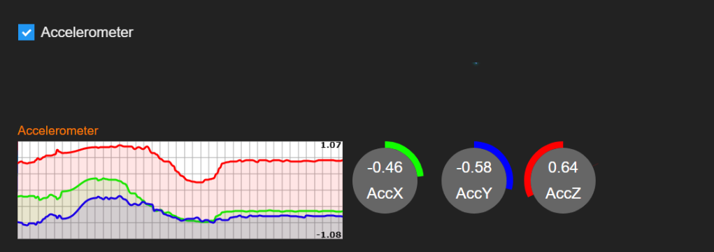
Accelerometer.
Display accelerometer value on 3 axis XYZ .
Unit: ( scale 0.1 m/s^2).
Applying filter to Euler Angle.
Besides keeping the Yaw value stable by selecting “Compass Calibrated for Yaw” mode (introduced above).
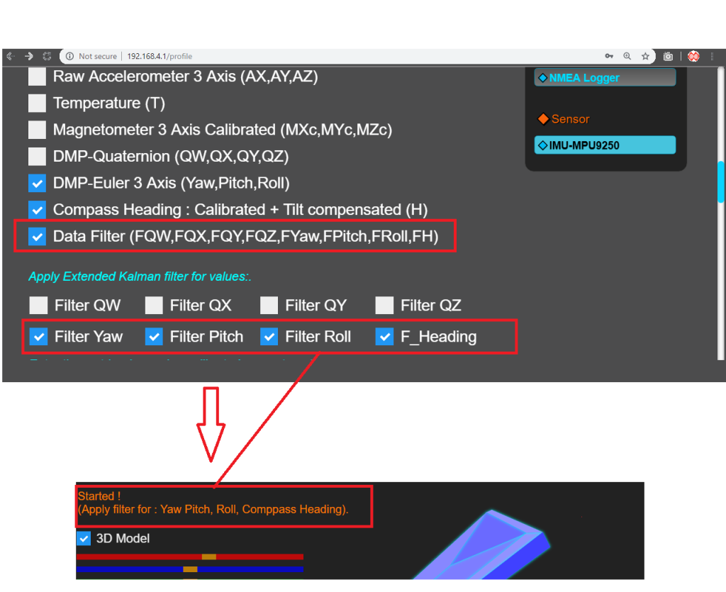
It is also possible to apply filters for Pitch-Roll-Yaw values to reduce noise by selecting ‘Filer Roll’, ‘Filter Pitch’, ‘Filter Yaw’ and ‘Filter F_Heading’ in the IMU-MPU9250 tab.
The name of the filtered values will be displayed when the IMU-Viewer restarts ( image above).
GNSS_VIEWER Introduce .
Message decoding tool NMEA / RTCM from GNSS positioning devices.
Connect the RX-UART1 port to the TX output of the GNSS device.
Select connection baudrate and screen update frequency then press connect.
For more detial about hardware connection, Click here.
Note: If the input is RTCM, ESPrtk 2.4.1 currently only recognizes RTCM 3.x but does not really resolve it because it is not fully supported yet.
If the input is NMEA, the following messages will be parse: RMC-GLL-GGA – GSA-ZDA-VTG-GSV.
IMU_VIEWER Introduce .
This feature is available on version 2.7.5 or higher.
Read data from MPU9250 and display as real-time graph, value bar and 3D model.
Video demo :
Wiring MPU9250 to use with ESPrtk
See the circuit diagram here : Export IMU Data to TX_UART_0 port .
3D Model.
Draw a 3D object simulation with rotation angle taken from Pitch-Roll-Yaw -Compass heading data.
The Camera’s viewing angle can be changed by using the Bias Yaw-Pitch-Roll value bars. (Default all Bias set to 0).
Euler Angle.
Display of 3 Euler angles: Yaw-Pitch-Roll.
Unit: degree.
Special :
The value of Yaw will drift after a long enough time even when the sensor is not moving or rotating.
Compass can be used as a Yaw value by selecting ‘Compass Calibrated for Yaw‘ mode.
In this way, the value of Yaw (in Euler Angle) and the rotation angle Z axis (in 3D Model) will be the compass value H (Magnetometer calibrated + Tilt compensation) or HF (Magnetometer calibrated + Tilt compensation +Kalman Filter) when the filter is applied.
However, before select this mode, make sure the compass has been calibrated by filling in the Transformation Matrix in ‘Profile -> IMU MPU9250’ tab.
To calibrate magnetometer on ESPrtk : IMU MPU9250 : Calibrate magnetometer on ESPrtk using Magneto1.2.
See more about H ,HF and Transformation Matrix here : Export IMU Data to TX_UART_0 port.
Gyroscope.
Display Gyro value on 3 axis XYZ .
Unit : Degree/second.
Accelerometer.
Display accelerometer value on 3 axis XYZ .
Unit: ( scale 0.1 m/s^2).
Applying filter to Euler Angle.
Besides keeping the Yaw value stable by selecting “Compass Calibrated for Yaw” mode (introduced above).
It is also possible to apply filters for Pitch-Roll-Yaw values to reduce noise by selecting ‘Filer Roll’, ‘Filter Pitch’, ‘Filter Yaw’ and ‘Filter F_Heading’ in the IMU-MPU9250 tab.
The name of the filtered values will be displayed when the IMU-Viewer restarts ( image above).
