
Steps to use ESPrtk.
Step 1: Prepare an ESPrtk board for the project.
Users can create for their own ESPrtk board according to 2 posts below.
Create an ESPrtk board from any ESP32 development boards.
Then upload firmware for ESP32’core , follow this link :
Register – Login -Update Firmware for ESPrtk.
Step 2: Activate ESPrtk.
Users will not need to do this when purchasing ESPrtk boards (hardware) from us.
However, if you are a DIY user who wants to save costs when using ESPrtk as a firmware file, we will require users to enable the function on ESPrtk before using it. See the instructions here :
Get KEY file to activate ESPrtk.
Step 3: Connect ESPrtk to RTK receiver.
ESPrtk can work with any RTK receiver that supports UART connectivity to send / receive data.
When using ESPrtk as a data transmission bridge, ESPrtk only needs up to 2 ports (1 for TX and 1 for RX) when connecting to RTK receiver.
In some cases when users want to use other features, some other ports will be added.
Visit this site to consult some connection diagrams:
Connect ESPrtk with RTK Receiver.
Step 4: Configure ESPrtk.
ESPrtk supports many features, users need to set (configure) to operate on ESPrtk before using.
ESPrtk supports configuration via web interface (Web Configure) or via UART connection (UART Configure) .
Step 5: ‘Plug and Play’.
After configuring ESPrtk, configuration information on ESPrtk will be stored in Flash of ESP32. Each time restart (power up or press the reset button), ESPrtk will retrieve the saved configuration information to run. That means users only need to configure ESPrtk once.
ESPrtk Understanding.
ESPrtk is ESP32 module.
It works similarly to RTK data transmission devices with wireless connections commonly found on complete RTK receivers.
It communicates with RTK receivers with UART communication. Using a variety of different transmission methods and models.
ESPrtk Pinout
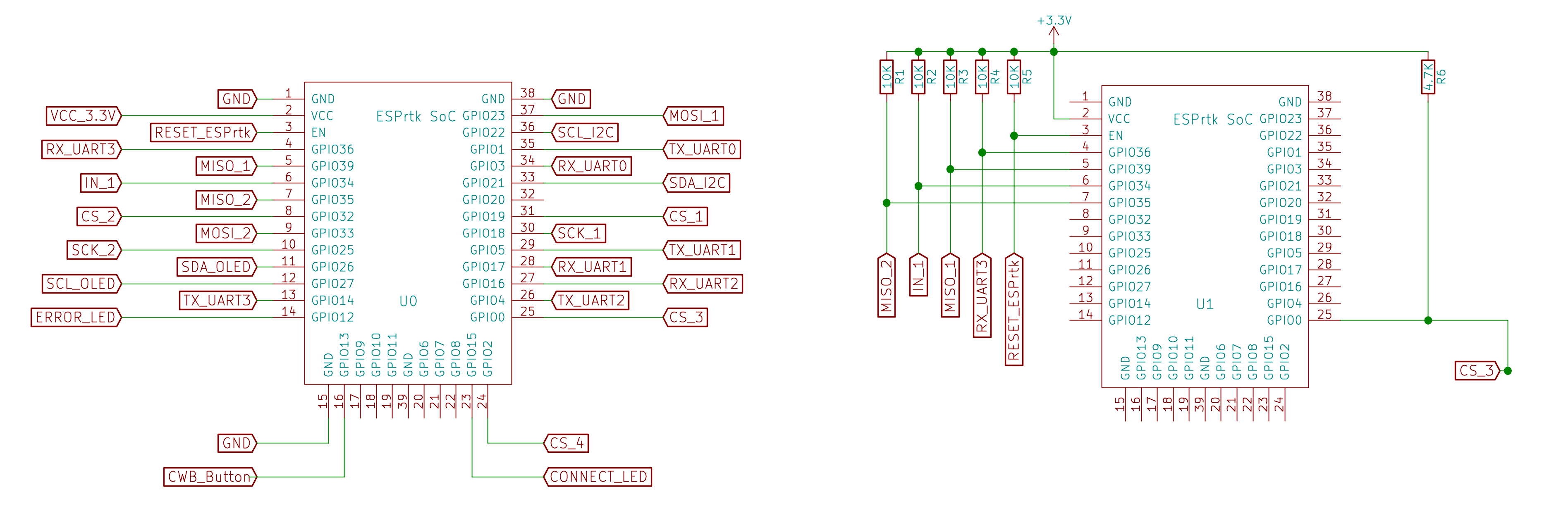
ESPrtk PinMap table
ESPrtk IO Name | GPIO | Input Pullup | Out | Type | Function |
VCC_3.3V | VCC | ● | ◌ | ◌ | Power input |
GND | GND | ◌ | ● | ◌ | Power ground |
RESET_ESPrtk | EN | ● | ◌ | Inerrupt | Reset ESPrtk |
ESPrtk IO Name | GPIO | Input Pullup | Out | Type | Function |
CWB_Button | 13 | ● | ◌ | Inerrupt | Hold to Start WEB Configure |
MOSI_2 | 33 | ◌ | ● | SPI | GPIO Reserve |
MISO_2 | 35 | ● | ◌ | SPI | GPIO Reserve |
SCK_2 | 25 | ◌ | ● | SPI | GPIO Reserve |
CS_1 | 19 | ◌ | ● | SPI | Connect to CS pin on SD /Micro SD Card module |
CS_2 | 32 | ◌ | ● | SPI | GPIO Reserve |
CS_3 | 0 | ◌ | ● | SPI | GPIO Reserve |
CS_4 | 2 | ◌ | ● | SPI | GPIO Reserve |
IN_1 | 34 | ● | ◌ | Inerrupt | GPIO Reserve |
ESPrtk IO Name | GPIO | Input Pullup | Out | Type | Function |
RX_UART0 | 3 | ● | ◌ | UART | Flash/Update Firmware .- Command control – IMU Output Connect to TX_UART pin on HOST |
TX_UART0 | 1 | ◌ | ● | UART | Flash/Update Firmware .- Command control – IMU Output Connect to RX_UART pin on HOST |
RX_UART1 | 17 | ● | ◌ | UART | Connect to TX_A_UART GNSS RTK Receiver |
TX_UART1 | 5 | ◌ | ● | UART | Connect to RX_A_UART GNSS RTK Receiver |
RX_UART2 | 16 | ● | ◌ | UART | Connect to TX_B_UART GNSS RTK Receiver |
TX_UART2 | 4 | ◌ | ● | UART | Connect to RX_B_UART GNSS RTK Receiver |
SCL_I2C | 22 | ◌ | ● | I2C / I2S | Connect to SCL pin on Other module ( IMU / Sensor / Clock ..) or Connect to NeoPixel Trips 4 LED |
SDA_I2C | 21 | ● | ● | I2C | Connect to SDA pin on Other module ( IMU / Sensor / Clock ..) |
RX_UART3 | 36 | ● | ◌ | UART | GPIO Reserve |
ESPrtk IO Name | GPIO | Input Pullup | Out | Type | Function |
MOSI_1 | 23 | ◌ | ● | SPI | Connect to MOSI pin on SD /Micro SD Card module |
MISO_1 | 39 | ● | ◌ | SPI | Connect to MISO pin on SD /Micro SD Card module |
SCK_1 | 18 | ◌ | ● | SPI | Connect to SCK pin on SD /Micro SD Card module |
CONNECT_LED | 15 | ◌ | ● | PWM | Connect to single LED (Pull Down) to show Connection Status |
ERROR_LED | 12 | ◌ | ● | PWM | Connect to single LED (Pull Down) to show Error Status |
TX_UART3 | 14 | ◌ | ● | UART | GPIO Reserve |
SCL_OLED | 27 | ◌ | ● | I2C | Connect to SCL Pin on OLED SSD1306 /SH1106 Display |
SDA_OLED | 26 | ● | ● | I2C | Connect to SDA Pin on OLED SSD1306 /SH1106 Display |
Hardware selection.
ESP32.
- Flash minimum 4MByte (32Mbit).
- Need to support external antenna connector.
- ESP32 needs in Revision 1 .
Since this is the latest silicon version, it fixed the errors on REV0. You can check it manually by going to the About tab on Webconfigure to view your ESP32 status.WebConfigure :About.

PCB Antenna or UFL – IPEX Connecter ?
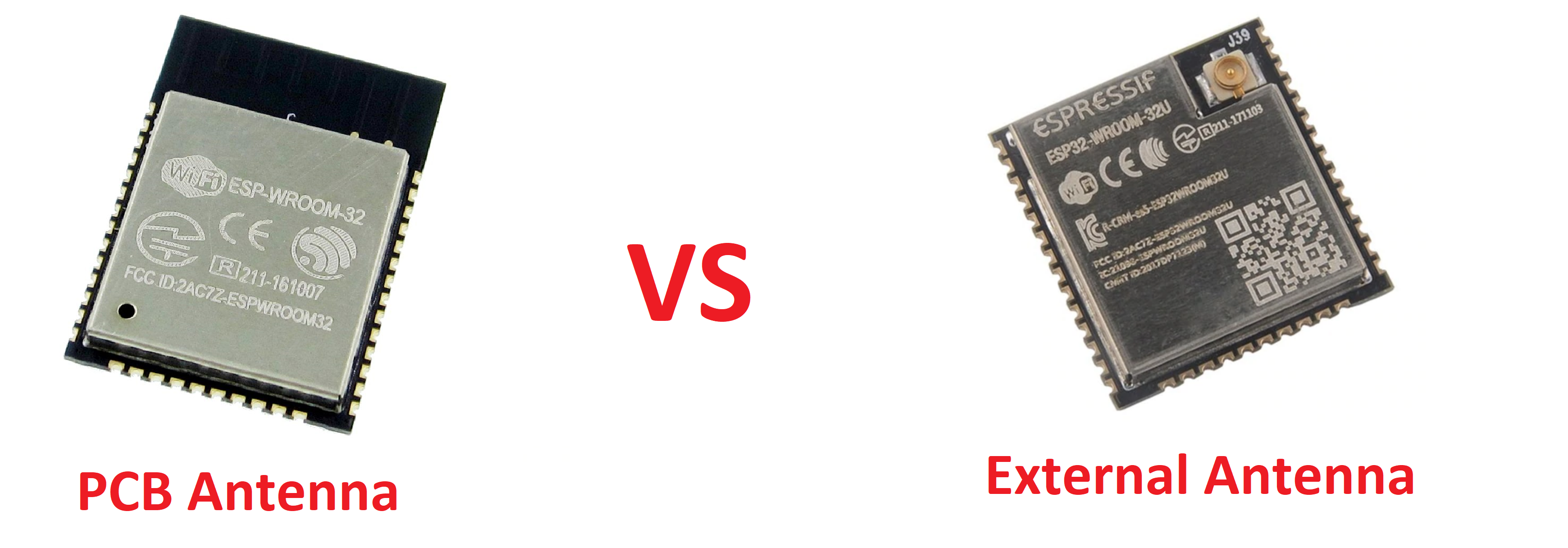
External antenna will give better signal quality than PCB Antennas.
PCB Antenna is compact and available on ESP32 chip.
If you select the External Antenna with U.FL or IPEX connection, caring for your U.FL connector is all about keeping that shiny electrical contact pristine and contacting! Grime, oxidation, and mountain dew will increase the impedance to/from the antenna and will reduce range.
Read more : Three Quick Tips About Using U.FL – From Sparkfun
SMA Wifi for External Antenna.
Anten 2.4Ghz 3dB to 5dB SMA with SMA to IPEX-UFL Adapter Cable will be the option.

Neopixel LED.
There are so many options with it.. But driver chip need is WS2812B (not WS2812)

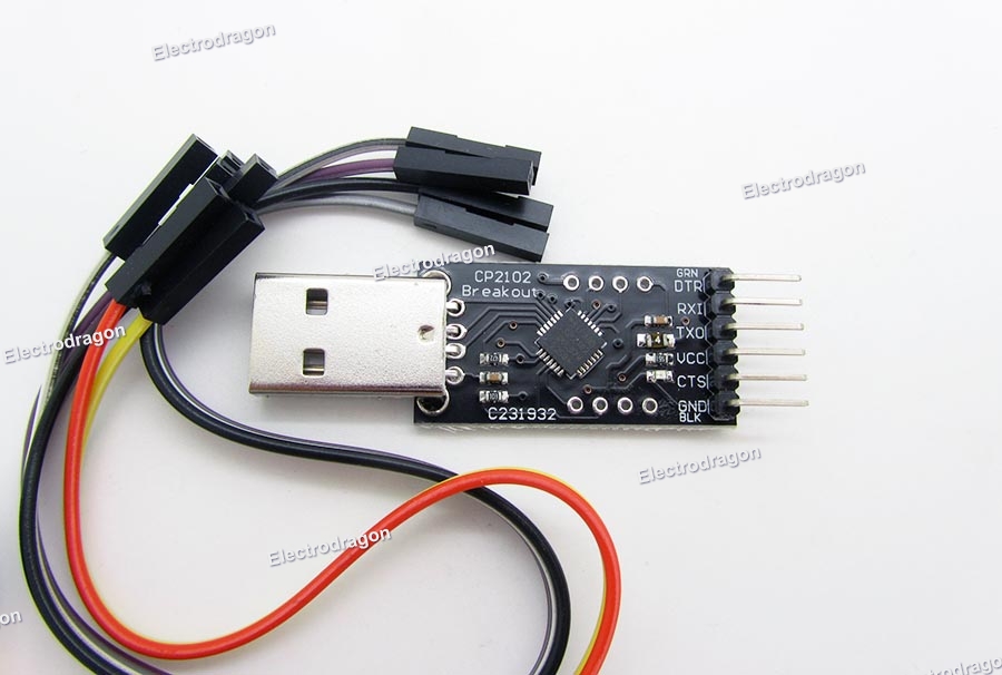
USB to UART module.
If your ESP32 board does not support USB port, you need to buy additional USB to UART module, like CP2102-USB-TTL-UART-Module-V2 as below , it will help you upload firmware to ESP32 and also helpful to use it to configure Ublox (or Navspark) module .
OLED SSD1306 0.96 inch.
ESPrtk higher 2.7.0 support SSD1306 128×64 0.96 inch ( SH1106 1.3 inch support only on higher 2.7.6 ) with I2C communicate.

When we mention “stable connection” it means that all other connections must also be stable, they include:
- Power supply for the whole system.
- Connect from ESPrtk to the router (Wifi or Ethernet cable).
- Internet access of routers.
- Electric wire
Power supply for the whole system:
ESPrtk V1 circuit board requires a 5V DC power supply (ESP32 module operates at 3.3Volt voltage by IC AMS1117 3.3) with a minimum current of 500mA.
Recommended power supply should be a DC battery or Power bank. Before the power input should add filters, they need to stabilize the voltage when ESPrtk starts wifi, they should support anti-short circuit, self-recovery fuse, anti-interference ….

During operation, if the power supply is turned off or the power is too low, ESPrtk will be restarted and a warning message will appear as shown above.
Connect from ESPrtk to the router:
For users using ethernet cables, the connection quality is reliable because the connections are transmitted directly by electrical wires, the maximum cable length should be within 30 meters.
With Wifi, users should pay attention to the maximum distance of wifi. Wifi ESP32 on ESPrtk will use the maximum transmit power of 20dB (100mA), with the distance to the router is up to 5m for open space and 1 meters for obstacles. (Do not risk putting them at a longer distance, no one can guarantee that the connection will always be reliable). If you cannot set ESPrtk closer, try to set the router closer to ESPrtk.
Internet access of routers:
Before using the internet for RTK systems, please make sure they are of good quality and are available 24 hours a day. For systems that operate continuously, it is necessary to take internet quality tests at many times during the day-week or even the month.
RTCM 3.3 data stream currently only requires less than 60Kbit / s (minimum of 10Kbit / s), however, you should not choose low-competitive networks. Please use internet service packages from 3G or higher.
Final is Electric wire:
At last but not least (You probably already know this, but you still need to pay attention because it’s a potential error). The connections will fail if the wires do not work properly, making sure the wires are connected by welding method.
Conclude : In general, the requirements should be implemented at any RTK system, if four requirements are met, ESP rtk will operate very stable without any error for a long time.
Wifi and Internet.
To access the internet via wifi, ESPrtk needs to connect to a WiFi access point (AP) or Hotspot.
By default, ESPrtk will support storing 3 different access points.
Before starting the connection, it will scan and select the access point with the strongest signal strength to connect to. If the connection fails, it will connect to the remaining network until the end.
If all have the same signal strength, it will connect to the access point that has a higher priority from 1-2-3 -… in the list.
If all connections to Hotspot fail, it will scan an open network (whose name matches the name of at least one of the 3 networks added to the list) and connect to it.
ESPrtk never connects to a network that has a different SSID name than the SSID name placed in the list, even if the network is open and available because this may be abused and misleading that everything is still working similar to the plan. (in fact is not).
Security.
ESPrtk needs to be worthy of what we expect from a high quality product. Security is a very important topic, ESPrtk will encrypt everything it can to minimize the impact of attacks, they include (in 2.4.1 Version):
- Setting data and user profile data.
- RTCM / NMEA data in MQTT service.
- UART data in UART bridge application.
In order to access these data, users need to create a profile account in ESPrtk, perform a login before starting changes on the data. If you are the owner of the account but forgot the password, the only way is to format the Flash chip (erase all data on the Flash chip) and Flash the firmware file again.
Security issues will not be mentioned much because this is a sensitive issue, we will not answer on this issue so don’t ask anything about it. Development team and me just want to say : “We are doing and will do the best things to protect your ESPrtk.”
Neopixel LED -WS2812B.
Neopixel is a neopixel led strip (WS2812B) consisting of 4 LED, each pixel will display only 4 colors as Green-Blue-Red-White. (White color is when all 3 Green-Blue-Red colors are turned on). Neopixel is supplied with 5V voltage, the input control terminal is connected to GPIO14 pin on ESP32 via a resistor from 50 Ohm to 220 Ohm. They have an order of 1-2-3-4. (LED1 is the LED is set to control the input data pins on it.)
To change Neopixel brightness, go to the ‘Display Viewer’ tab :
WebConfigure:Display viewer.
Neopixel LED and debugging.
When using ESPrtk, users will set action targets for ESPrtk by configuring the Action Plan.
However, when one or more goals are not achieved, then an error will appear. ESPrtk will report an error and wait for the user to resolve the error before continuing its work.
To inform users that an existing error , ESPrtk will display on the LCD screen, change the color of the LED, make a sound from the buzzer … to catch attention to the user.
If you do not have much experience when using ESPrtk, the error will always occur, but do not be too afraid when you constantly see errors because all of them have causes and always have ways to solve them.
How does ESPrtk show errors?
Error in ESPrtk decentralized and zoned. When an error occurs, it is assigned an ID and exported to UART0. ESPrtk flashes the error status LED and displays it with Neopixel lights by changing colors on them.
If more than one error occurs, they will be included in the error stack, errors with more important elements will be displayed first, users need to fix the errors until all errors are removed.
What should I do when I see an error?
ESPrtk will try to fix the error and try again when it fails, if successful, the error will be removed.
ESPrtk will definitely have an error if the LED error state flashes quickly, if they blink slowly, it means ESPrtk still runs perfectly without errors (even if the LED Neopixel has the same color as one error because Neopixel will slower update Led error).
However, if ESPrtk regularly reports an error:
The first thing to do is to determine what this error is, if you connect the UART0 to terminal display then this error will be displayed as a text with a hint of error resolution. If UART0 cannot be used to collect ESPrtk status. Please collect colors on NEOPIXEL and use the converter tool from color to error.

See : WebConfigure: Simple Debug.
Online Tool Debug (webpage ): esprtk.wap.sh
Download offline Tool Debug(webpage): Download and Documents.
If collecting colors makes it difficult for you, use the system logger:
See : WebConfigure: Event Log.
If you use an OLED screen instead of a Neopixel LED, you can see an error in the form of ID in the top right corner of the screen. Learn more about OLED display .
Automatically recover connections.
During operation, when the lost connection is detected (both wired connection like UART-SPI-Ethernet-I2C .. and wireless like WIFI-Radio Wifi – Bluetooth ..) , ESPrtk will automatically (try) to restore the connection. This means that the RTK system using ESPrtk will never freeze (stop working) and users do not need to press the Reset button on ESPrtk to debug.
Instead, when receiving the connection error message on ESPrtk, the user needs to provide and resolve the requests given by ESPrtk (via suggestions using the Simple Debug tool, see above), At the same time, ESPrtk will repeat check process until that problem was solved by the user.
Connection recovery time since the error was resolved until ESPrtk returned to normal status (without any errors) equal to the normal connection time.
To ensure safety for both you and the circuit board when fixing wired connection errors, we recommend turning off the system and cut power supply before any action is taken.
Status LED.
Both two LED is activated at a high level of 3.3v, Anot input is connected to a resistor from 220Ohm (to 2K Ohm), Katot is connected to GND.
Connection Status LED:
- Connected to the GPIO 15 pin, it should be Blue color when lighting.
- Fast blink with frequency of 4hz (high 50%) (cycle of 0.25s): a stable connection in RTK data transmission is established. For MQTT / NTRIP application, it means ESPrtk has successfully connected to the service provider. For RTK Offline Wifi, it means ESPrtk receives data from another ESPrtk. For Bluetooth Bridge, it mean has Bluetooth Client connect to ESPrtk.
- -Slow blink with 4-second cycle (high 10%): RTK data transmission connection has not been established.
- Fading : The ESPrtk program goes into deep sleep and doesn’t do anything more. That may be when a certain job is completed or ESPrtk notices that it should not continue for some reason.
- Light forever: WEB configure mode via WifiAP (or UART configure) is set up successfully, ready for users to access.
- No light after a long period of 10 seconds: connecting from GPIO15 port to this led is broken or ESPrtk has not been powered.
Error Status LED:
- Connected to the GPIO 2 pin, it should be Red color when lighting.
- Fast blink with frequency of 4hz (high 50%) (cycle of 0.25s):: At least one error needs to be fixed.
- Slow blink with 4 seconds cycle (high 10%): No errors, stable operation.
- No light after a long 10s time: Connecting from GPIO3 pin to this led is broken or ESPrtk has not been powered.
Device_ID
Each ESPrtk module will be assigned an ID.
The ID on each ESPrtk is not the same. They are displayed with characters in the range A-> Z, a-> z, 0-> 9 and 2 marks “-” and “_”. With the number of characters from 5-> 7 characters.
Where to find Device ID: It appears in Wifi webconfigure station name, in the Bluetooth Master name, in the top left corner of the configure web page, in check ESP32 status at About page webconfigure.. ..
ID used to distinguish ESPrtk devices from each other, it is also used to name the wifi station configuration, client ID for MQTT, client ID for NTRIP base, client ID for Wifi-TCP, name for activate file. ..
Device ID should be collected and stamped on each ESPrtk module.
Device ID cannot be changed.
UART ports.
UART port 0:
- Baudrate default : 230400 bps.
- Baudrate range: 57600-115200-230400-460800 bps.
- TX_UART 0 – GPIO1 -ESP32: (Output) ESPrtk status, NMEA from Rover, MQTT BROKER state (ESPrtk as Base / Rover)
- RX_UART 0 – GPIO3 -ESP32: (Input) None.
UART0 is also the port to load the program for ESP32 module.
UART port 1:
- Baudrate default : 57600 bps.
- Baudrate range: 57600-115200-230400-460800 bps.
- TX_UART 1 – GPIO5 -ESP32: (Output) Navspark / Ublox config
- RX_UART 1 – GPIO17 -ESP32: (Input) Navspark / Ublox config, RTCM / NMEA input (RTCM / NMEA from TX GPS module); (ESPrtk as Base / Rover)
UART port 2:
- Baudrate default : 57600 bps.
- Baudrate range: 57600-115200-230400-460800 bps.
- TX_UART 2 – GPIO4 -ESP32: (Output) RTCM output (esp32 as Rover)
- RX_UART 2 – GPIO16-ESP32: (Input) None
Supported Baudrate speed is 57600-115200-230400-460800 bps.
UART ports should be connected to Pull_up LEDs to see data transmission status.
The baudrate rate on UART ports really affects the processing speed and RTCM / NMEA data transfer rate.
If possible, the UART0 baudrate speed will be set as high as possible.
The baudate rate of UART1 and UART2 should not be too low, recommend at 57600 bps or higher.
I2C port.
- I2C Used to connect to MPU9250 Sensor or communicate using I2C.
- I2C_2 Used to connect to OLED Display or communicate using I2C.
SPI port.
Used to connect to an SD Card , or Ethernet module or communicate using SPI .
GPIO0
Used to load the program for ESP32 by connecting this pin to 0V before pressing the Reset button. See more: Flash/upload -Update Firmware for ESPrtk.
Or used as CS pin (Chip Select) for SD Card in SPI communicate.
Support Custom Pinmap
This is a feature available on version 2.7.2. It allows users to change the output configuration on GPIO pins of ESPrtk.
In this way, the selection and placement of the output pins on ESP32 will not depend on the default configuration, making it easier for users to redesign their own ESPrtk PCB board.
Read more: ESPrtk support custom pinmap .